Page 12
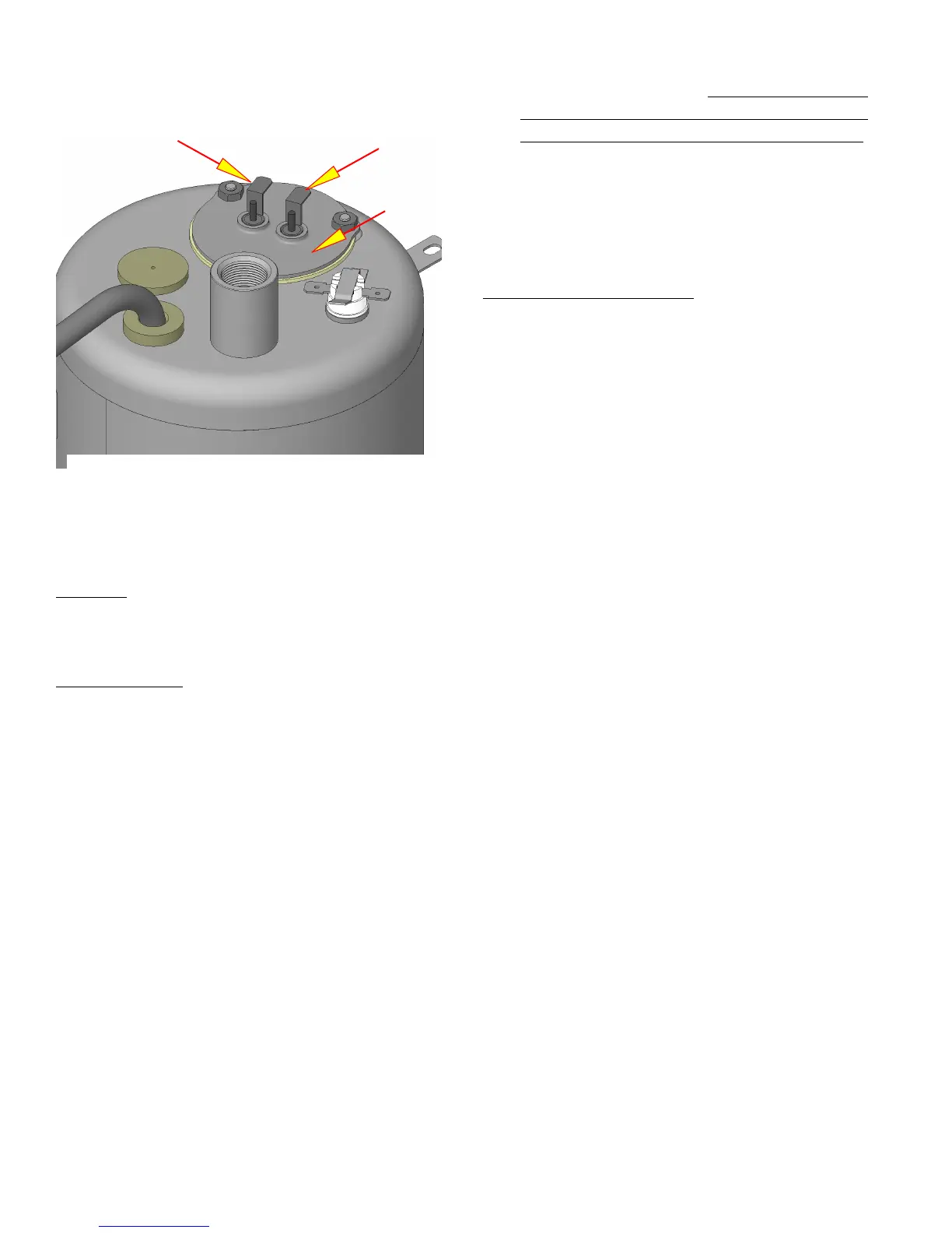
TANK HEATER
Location:
The tank heater is located inside the tank
and secured to the tank lid.
Test Procedures:
1. Disconnect the brewer from the power supply.
2. Check the voltage across the black and white
wires on 120 volt models or the black and red
wires for 220 volt models with a voltmeter. Plug
the brewer into the power source. The indication
must be:
a) *120 volts ac for 120 volt models.
b) *220 volts ac for 220 volt models.
(* Control thermostat must be turned on)
3. Disconnect the brewer from the power source.
If voltage is present as described, proceed to #4
If voltage is not present as described, refer to the Wir-
ing Diagrams and check wiring harness.
4. Disconnect the wires from the heater termi-
nals.
5. Check for resistance across the tank heater ter-
minals.
a) 11 ohms (±10%) for 120 volt models.
b) 26 ohms (±10%) for 220 volt models.
SERVICE (cont.)
c) Infinite resistance between either terminal to
the housing for all models. Any resistance reading
to housing indicates heater is cracked allowing
water to short the circuit and must be replaced.
If resistance is present as described, reconnect the
wires, the tank heater is operating properly.
If resistance is not present as described, replace the
tank heater.
Removal and Replacement:
1. Remove the tank inlet fitting securing the fill
basin to the tank lid, remove fill basin and tank
inlet gasket. Set all three parts aside for reas-
sembly.
2. Disconnect the black wire on the terminal block
from the tank heater and disconnect the blue/
black wire from the limit thermostat or thermal
cut-off to the control thermostat.
3. Disconnect the black wire and the white or red
wire from the tank heater terminals.
4. Remove sprayhead and the hex nut securing
the sprayhead tube to the hood. Set aside for
reassembly.
5. Remove the eight #8-32 nuts securing the tank
lid to the tank.
6. Remove the tank lid with limit thermostat or ther-
mal cut-off, sprayhead tube and tank heater.
7 Remove the two hex nuts securing the tank heater
to the tank lid. Remove tank heater with gaskets
and discard.
8. Install new tank heater with gaskets on the tank
lid and secure with two hex nuts.
9. Install tank lid with limit thermostat or thermal
cut-off, sprayhead tube and tank heater using
eight #8-32 hex nuts.
10. Secure sprayhead tube to hood using a hex
nut.
11. Install sprayhead.
12. Reconnect the wires to the limit thermostat or
thermal cut-off, tank heater and control thermo-
stat. See limit thermostat, thermal cut-off and
control thermostat sections in this manual when
reconnecting wires.
13. Install fill basin, secure with tank inlet fitting and
gasket.
14. Refer to wiring diagram when reconnecting the
tank heater wires.
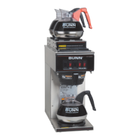
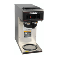
FIG. 12-1 TANK HEATER
41667 102708