16
Part Material
Female EN 175301-803
fixed connector
PA6
PG9 cable gland PA6 or polyarylamide
M3x45 or M3x55 screw 1, in stainless steel AL2
Seal for the female fixed
connector
NBR
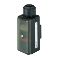
32,5
90
36
21
Fig. 3: Dimensions [mm] of the 1078
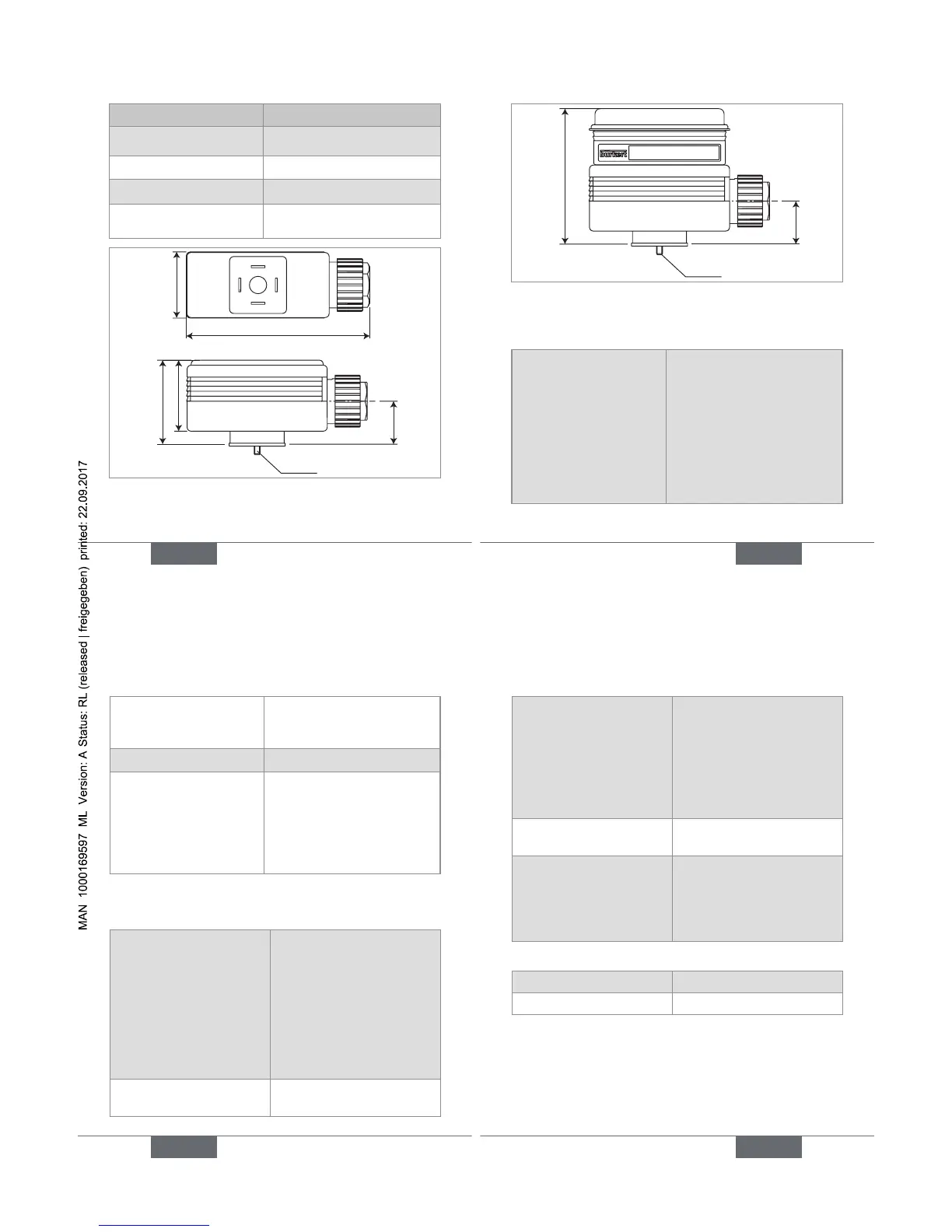
Fig. 4: Dimensions [mm] of the 1078-2 combined with
the 1077-2
6.2.2. General features
Time range (1078-1)
(mechanical adjustment
using the 6 switches N°
1, 2, 3, 6, 7 and 8)
• 0,5 to 10 s (default setting)
• 1,5 to 30 s
• 5 to 100 s
• 0,5 to 10 min.
• 1,5 to 30 min.
• 5 to 100 min.
• 12 to 240 min.
• 0,5 to 10 h
18
Time range (
1078-2)
(digital adjustment through
module 1077-2)
0,2 s to 9999 h, continuous
Tolerance (1078-2) 1 %
Resolution (1078-2)
• up to 199 s
• up to 199 min.
• up to 99 h
• up to 9999 h
• 10 ms
• 1 s
• 1 min.
• 1 h
6.2.3. Electrical data
Table 1: Electrical data of the 1078
Power supply
• 1078-1
• 1078-2
Tolerance 10 %
• 12-24 V DC, max. 2 A
or 24-48 V AC/DC, max
1,5 A or 110/230 V AC,
max 0,5 A
• 12-24 V DC, max. 2 A
or 24-48 V AC/DC, max
1,5 A
Protection against polarity
reversal
No, for devices energized
with a direct voltage
19
Power supplied to the
solenoid valve
• Version 12-24 V DC
• Version 24-48 V AC/DC
• Version 110/230 V AC
• 12-24 V DC, max. 2 A
• 24-48 V DC, max. 1,5 A
• 110/230 V DC, max.
0,5 A
Clearance and leakage
path
Acc. to VDE 0100
Electrical connection
• Cable diameter
• Cross section of the
wires
Through PG9 cable gland
• 6 to 7 mm
• max. 1,5 mm
2
Table 2: Electrical data of the 1077-2
Supply voltage Energized by the 1078-2
Power consumed 5 mW
 Loading...