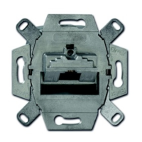
Fig. 4: Connection of assembly
9. Position the connection assembly.
10. Feed the twisted pairs with screen laterally through the assembly.
– The sockets must always point down.
11.Press the assembly together.
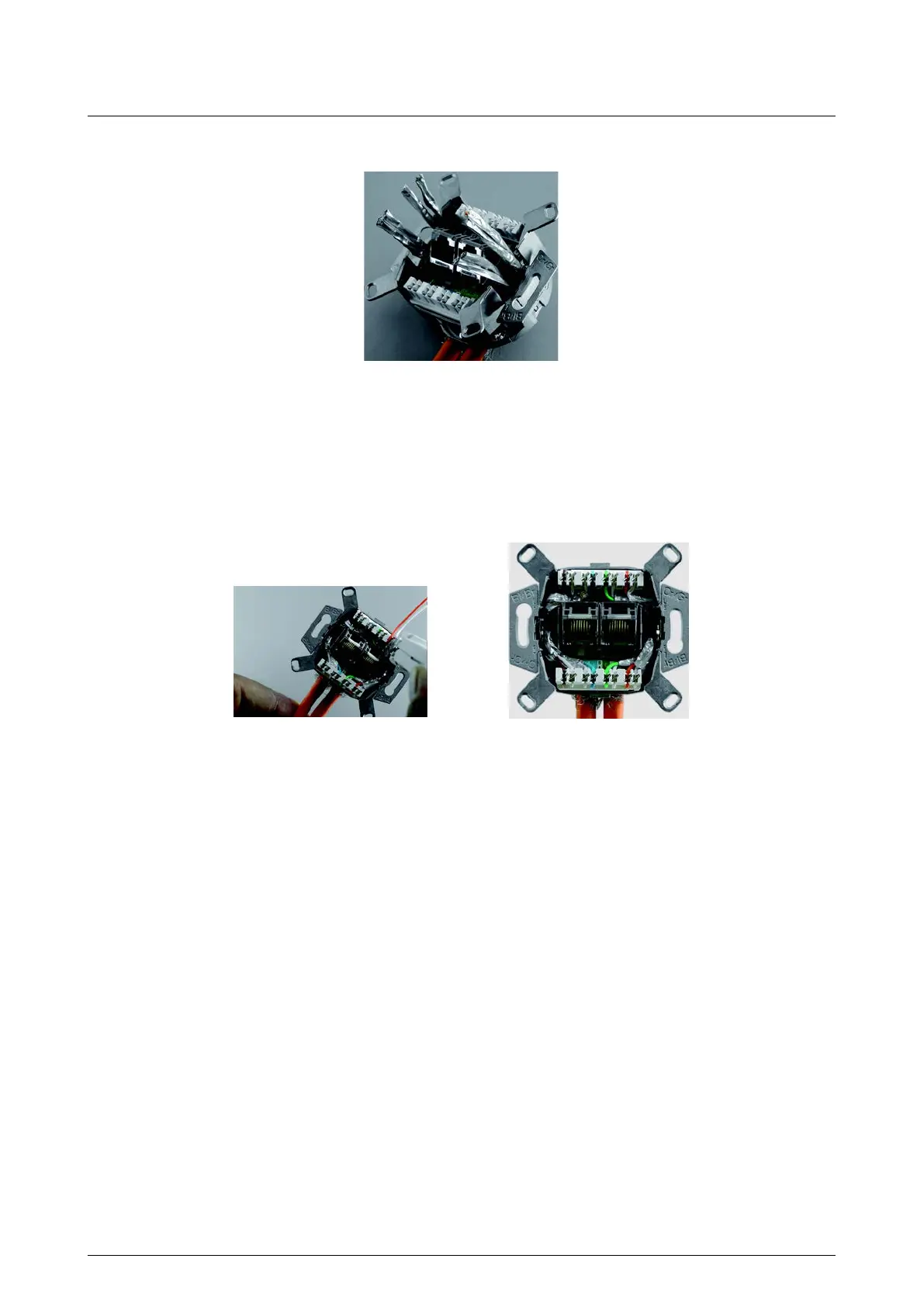
Fig. 5: Positioning the wires
– Maintain the pairs screen and the twist of the pairs as long as possible.
– Adhere to the assignment according to the colour code in the patch bay and on the socket (see chapter
"Colour code").
12. Install the wires from the centre to the outside.