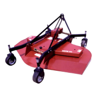
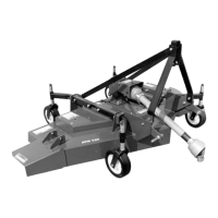
ASSEMBLY
DHM7 05/21 Assembly Section 3-3
© 2021 Alamo Group Inc.
ASSEMBLY
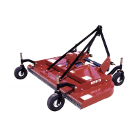
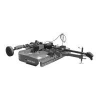
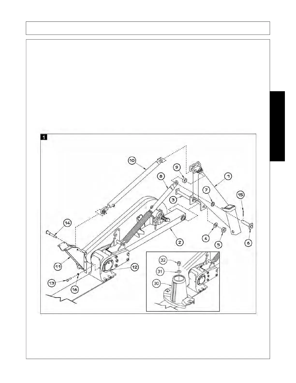
Refer to fig. 1 and carry out the following steps in the order indicated:
1. Use special nut 32 and special washer 31 already in the spindle to mount disc-conveyor 30 (dynamometric
spanner set at 32 kgm \320Nm torque) in the cutterbar (see picture detail). Pay attention to discs layout,
see fig.15.
2. Use pin 3 - D 30 x 178 (D 1”3/16 x 7”) to insert support 1 into the special slot on frame 2 and fasten with
washer 4 (DIN 125A) and nut 5 - M 20 (D 3/4”).
3. Use the four screws 13 M 12 x 30 (D 1/2” x 1”11/64) and helical spring lock washers 16 (similar to DIN
127B) to mount support 11 on gear box 12.
4. Use pin 6 D 30 x 106 (D 1”3/16 x 4”) to insert distance washer 7 D 30 - 42 x 5 (D 1”3/16 - 1”5/8 x 3/16”), tie
rod 8, distance washer 9 D 30 - 42 x 10 (D 1”3/16 - 1”5/8 x 3/8”) and hydraulic cylinder 10 into the special
slot on support 1 and fasten into position with peg 15 D 8 x 50 (D 5/16” x 2”).
5. Use pin 14 D 25 - 19 x 45 - 67 (D 1” - 3/4” x 2” - 2”3/4) to insert hydraulic cylinder 10 into support 11. Do not
fasten at this stage.