ASSEMBLY
DHM7 05/21 Assembly Section 3-4
© 2021 Alamo Group Inc.
ASSEMBLY
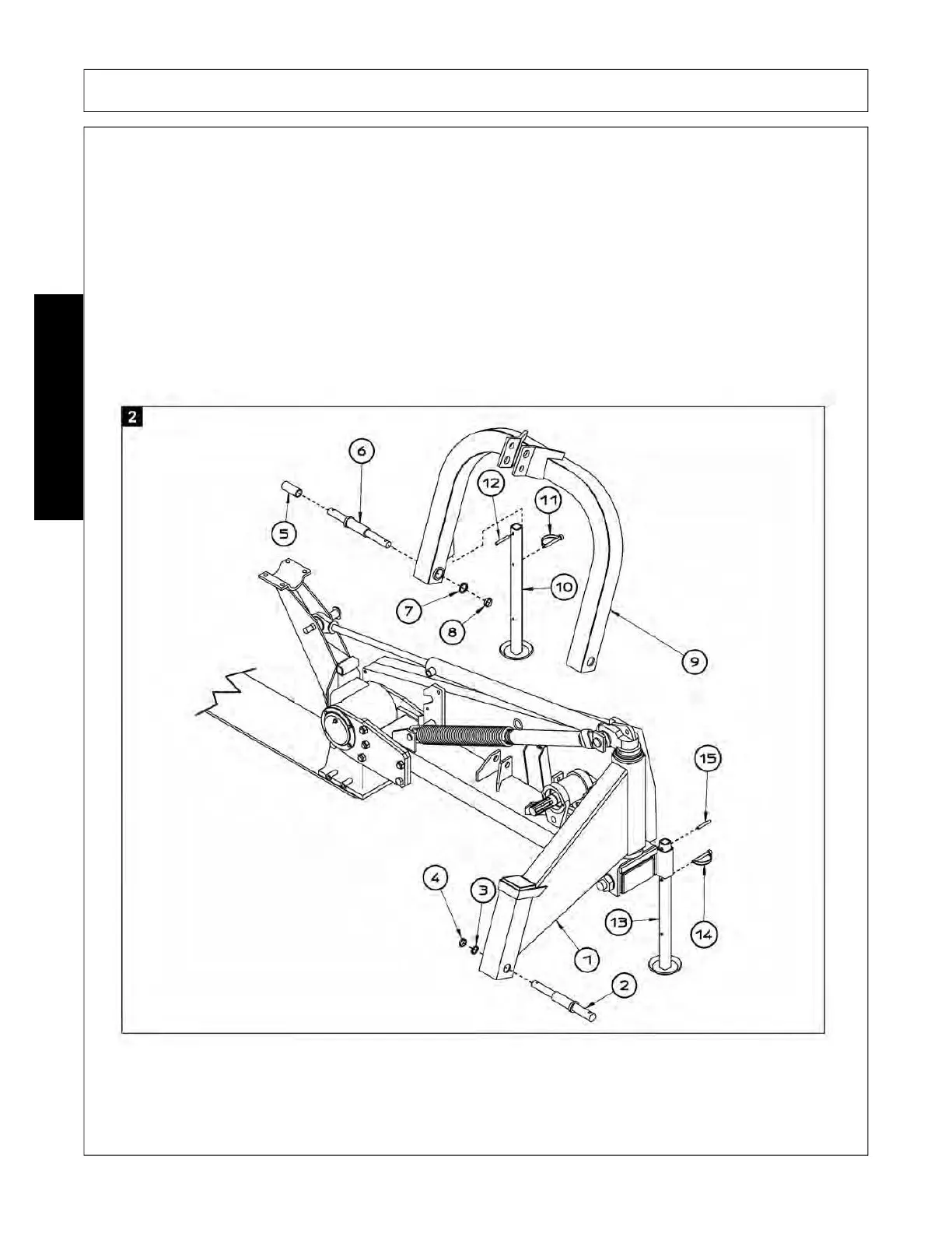
Refer to fig. 2 and carry out the following steps in the order indicated:
1. Insert rest foot 13 into the slot on support 1 and fasten into position with pegs 14 and 15 D 8 x 50 (D 5/16”
x 2”).
2. Use pin 2 D 28 - 30 - 22 x 260 (D 1”1/8 - 1”3/16 - 7/8” x 10”1/4) to insert arc 9 into the slot on support 1 and
fasten into position with washer 3 and nut 4.
3. Insert rest foot 10 into the slot on arc 9 and fasten into position with pegs 11 D 8 x 50 (D 5/16” x 2”) and 12.
4. Insert pin 6 D 22 - 30 - 22 x 260 (D 7/8” - 1”3/16 - 7/8” x 10”1/4) into the slot on arc 9 and fasten into posi-
tion with washer 7 (similar to DIN 127B) and ring nut 8.
5. Insert bushing 5 D 22 - 28 x 45 (D 7/8” - 1”1/8 x 1”3/4) into pin 6 for coupling (2nd class) to the tractor.