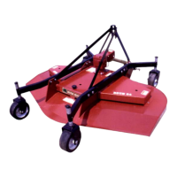
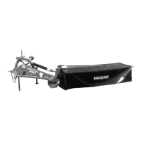
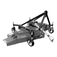
ASSEMBLY
DHM7 05/21 Assembly Section 3-7
© 2021 Alamo Group Inc.
ASSEMBLY
Refer to fig. 5 and carry out the following steps in the order indicated:
1. Mount the main tube 1 on the frame, move it on to flange 2 and 3 assembled with screws 4 M 12 x 55 (DIN
931), nuts 6 (M12) and flat washers 5 (DIN 125A), and at the same time insert the curved tube 16 into the
relevant hinge 18; do not tighten the set of screws 3-4-5-6 for the time being; make sure that the position-
ing tooth on tube 1 is held in the horizontal connection plane of flanges 2 and 3.
2. Insert tubes 7 and 10 into support 21 (DHM 7).
3. Insert the curved tubes 8 and 9 into the slots on tubes 10 and 7.
4. Mount the assembly set 7-8-9-10-21 on to the load bearing tube 1 connecting with welded screws 13 and
use flat washers 11 and nuts 12 to tighten.
5. Insert tubes 14 and 15 into support 22 (DHM 7).
6. Insert assembly set 14-15-22 into hinge 18 connecting with load bearing tube 1.
7. Use washer 19 (DIN 125A) and nut 20 (M10) to tighten hinge 22 into slot 18.
8. At the same time insert the curved tube 16 in to the relevant hinge 18 and into tubes 14 and 15 and use flat
washer 19 (DIN 125A) and nut 20 (M10) to tighten the hinges in the corresponding slot 18.
9. Carry out the same operation with curved tube 17, hinge 18, washer 19 (DIN 125A) and nut 20 (M10).
10. Use screws 24 M 8 x 25 (DIN 933), washer 25 (DIN 125A) nut 26 (M8) to mount support 23 in the curved
tube 9.
11. Mount conveyor 37 in the support 27 with screw 34 M 10 x 35 (DIN 933), washer 31 (DIN 125A), and nut
30 (M10). Also use screw 38 M 12 x 35 (DIN 933) and nut 39 (M12). Use the slot 35 to change the position
of conveyor.
12. Mount screw 28 M 10 x 20 (DIN 933).
13. Secure the curtain 30 with front protection flipped towards the rear lacing ALL the straps 31 on the under
side of the curtain (see figure detail).
14. (OPTIONAL) Mount conveyor 33 in the support 36 of screw 34 M 10 x 35 (DIN 933), washer 31 (DIN
125A), and nut 30 (M10); also use nut 39 (M12). Use the slot 35 to change the position of conveyor.