831 N Central Ave Wood Dale Illinois 60191-1219 Tel 630@238@1183 Fax 630@238@1186 E-mail bencher@bencher.com www.bencher.com
00236IZV 100700-1-
Instructions
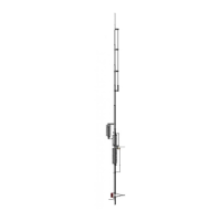
Model CPK
The CPK Capacitive Counterpoise Kit is a simulated ground system that allows the Butternut HF6V,
HF9V and related models to operate with low SWR on the bands for which they are designed. It may
also be used with conventional (trapped) quarter-wave verticals for low SWR operation on most bands,
although it was not designed with these types in mind and no information is available concerning its
compatibility with specific models. The CPK is not a substitute for a system of radial wires because it is
only partially effective in reducing the earth losses that can turn vertical antennas into inefficient
radiators. It is, rather, an electrical substitute for the "missing" half of a dipole antenna in that the
conductors of the counterpoise system in conjunction with the matching section of transmission line
provided contribute enough reactance to resonate the entire structure as an electrical halfwave.
WARNING: THERE IS VERY LITTLE RADIATION FROM THE CPK BUT HIGH RF
VOLTAGES CAN APPEAR ON IT ESPECIALLY WHEN HIGH POWER IS USED
AND THE POSSIBILITY ALWAYS EXISTS THAT POWER LINE VOLTAGES CAN
APPEAR ON UNLESS THE ASSOCIATED STATION EQUIPMENT IS CONNECTED
TO A GOOD EARTH GROUND. THEREFORE THE ANTENNA MUST BE PLACED
HIGH ENOUGH ABOVE THE EARTH SO THAT NO PART OF IT CAN COME INTO
CONTACT WITH PASSERS-BY AND THAT ANY SUPPORTING METAL
STRUCTURE SUCH AS A TOWER OR A MAST BE CONNECTED TO A GOOD
EARTH GROUND.
Neither the antenna proper nor the counterpoise assembly (which will be insulated from its supporting
structure) should be placed at DC ground potential during normal operation.
ASSEMBLY
Refer to your antenna assembly instructions. Only tube w/insulator (A) need to be considered during the
assembly phase of the counterpoise installation.
G 1. Insert the insulator end of tube w/insulator (A) into the bottom of tube (AA). Pass a 1-1/4"
screw through both parts and secure with a lock washer and hex nut.
NOTE: Coil (Q) base matching is NOT to be used for the CPK. Save it for possible future use.
G 2. Slide reinforcing tube (AB) around tube (AC).
G 3.
Insert the end of tube (AD) with the hole furthest from the end into one side of tube (AC). Pass
a 1" screw through both parts and secure with a lock washer and hex nut.
G 4.
Repeat step 3 for the other end of tube (AC).
G 5.
Insert the end of tube (AE) with the hole furthest from the end into tube (AD). Pass a 3/4" screw
through both parts and secure with a lock washer and hex nut.