05 06
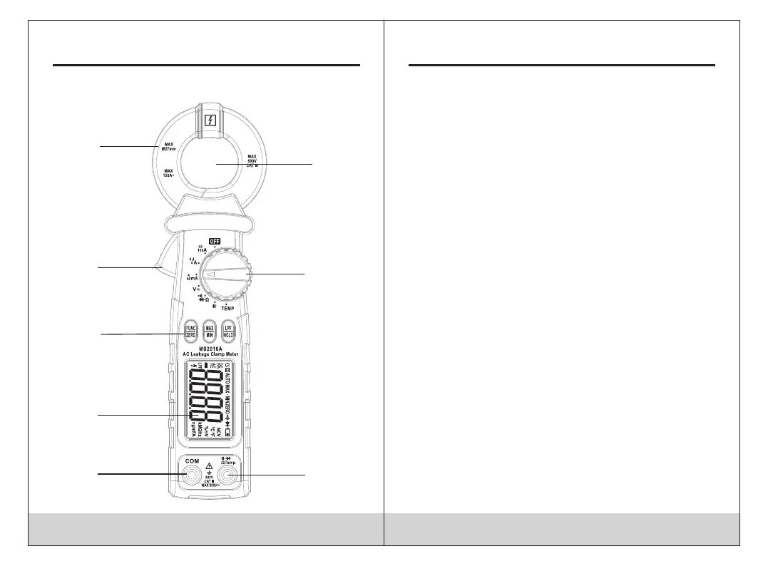
2.1 Part Name
5
6
7
3
4
8
2
1
(1) The central of the clamp head
(2) Transfer switch
(3) Resistance, capacitance, voltage,
diode and continuity input jack
(4) Common end jack
(5) LCD display
(6) Function choice button
(7) Trigger
(8) Current clamp head: used for leakage current
measurement.
2.2 Switch, Buttom and Input jack description
HOLD/LPF button: used for reading hold and LPF(50Hz/
60Hz) function control.
FUNC/ZERO button: used for measuring function switch
and current clearing function control.
MAX/MIN button: used for maximum/minimum
measurement function switch and leakage current
measeuring.
OFF position: used for shutting off the power.
INPUT jack: voltage, resistance, capacitance, diode,
circuit connection input wire connecting and
temperature terminal.
COM jack: voltage, resistance, capac
itance, diode,
circuit connection common wire connecting and
temperature terminal.
Transfer switch: used for selecting function and
measuring range.
29 30
Leakage Clamp Meter Leakage Clamp Meter
 Loading...