continuity measuring state.
4) Connect the probe to the both ends of circuit to be
tested for measurement.
5) If the resistance of circuit to be measured is less than
50Ω, the meter's built-in buzzer may sound.
6) Read the circuit resistance value on the LCD.
Note:
If the probe is open or circuits resistance to be tested is
more than 400Ω, the display will show “OL”.
4.13 Capacitance Measurement
Electric shock hazard.
To avoid electric shock, before measuring
capacitance, discharge capacitance completely.
1) Insert black probe to jack, insert red probe to“COM”
jack.“INPUT”
2) Measuring switch is placed to position .
3) After discharging capacitance completely, connect the
probe to the both ends of capacitor to be tested for
measurement.
4) Read the capacitance on the LCD.
To improve the accuracy below 1nF measuring value,
subtract the distributed capacitance of meter and cable.
Note:
Warning
4.14 Temperature Measurement
1) Measuring switch is placed to position .
2) Connect negative and positive end of K-type
thermocouple to “COM” jack and “INPUT” jack.
3) Place K-type thermocouple to the object or
environment to be measeured.
4) Read measured resuit from LCD display.
5.1 Replacing The Batteries
WARNING
To avoid electric shock, make sure that the test
leads have been clearly move away from the
circuit under measurement before opening the
battery cover of the meter.
WARNING
Do not mix old and new batteries. Do not mix
alkaline, standard (carbon-zinc), or rechargeable
(ni-cad, ni-mh, etc) batteries.
5. Maintenance
4.12 Circuit Continuity Measurement
Warning
Electric shock hazard.
When measuring circuit continuity, determine that the
power supply is disconnected and the capacitor in the
circuit is completely discharged.
1) Insert black probe to “COM” jack, insert red probe to
“INPUT” jack.
2) Measuring switch is placed to position .
3) Press “FUNC/ZERO” key to switch to circuit
forward voltage drop.
2) If the probe has reverse connection or the probe is
open, the LCD will show “OL”.
17 18
41 42
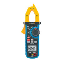
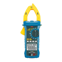
Leakage Clamp Meter Leakage Clamp Meter
 Loading...