Do you have a question about the C-Max CM2 and is the answer not in the manual?
The acoustic sensor head that transmits pulses and receives echoes.
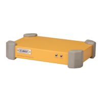
Surface electronics unit providing power, receiving data, and sending commands to the towfish.
Optional waterproof enclosure for the STR, providing waterproof connectors.
All-in-one data acquisition unit with integral PC, for exposed environments.
All-weather data acquisition unit using a ruggedized laptop PC.
Single pair of electrical conductors for data and power, offered in soft or steel-armoured types.
Optional items like winches, wing depressors, and brackets are detailed in later sections.
Major component specifications are listed in Section 15.
Setting up the PC, software, and connecting the STR or C-Shell via USB.
Guidance on routing, pulley placement, and securing the tow cable.
Methods for securing soft tow cables and avoiding damage.
Steps for connecting the tow cable and safety lanyard to the towfish.
Detailed steps for connecting the safety lanyard and tow cable extension to the towfish.
Securing the towfish bail arm using a breakable washer and cap screw.
Verifying system power and towfish energizing/connecting sequence.
Carrying spare breakable washers and the required 5mm hex key for operation.
Importance of advance planning for surveys and search operations.
Defining frequency, range, and overlap for complete coverage.
Considerations for survey line direction based on currents and bathymetry.
Ensuring transducers are angled correctly and the bail is attached.
Adjusting transducer angle for optimal range or surface reflection reduction.
Referencing Section 18 for advice and warnings on using the wing depressor.
Procedures for launching the towfish astern at slow speed, avoiding slack cable.
Setting altitude, locking bottom-tracking, and using force up/down controls.
Procedure for slowing down, washing, and capping connectors after use.
Steps to take if the towfish hits an obstruction and breaks the washer.
Using the plotter window to show waypoints, tracks, and swept ground.
Importance of helmsman skill for image quality, straight flight, and avoiding distortions.
Procedures for rising towfish, increasing speed, or avoiding propeller entanglement.
Commands supported by acquisition software for start, stop, range, and bottom-tracking.
Using up/down controls to force indicated altitude for altimeter lock.
Disabling acoustic transmissions for diagnostics or interference avoidance.
Using towfish at less than normal altitude limit for very shallow water.
Fixing gain profile, disabling altitude measurement, and adjusting gain.
Understanding the central track line, water column, and bottom echoes.
Interpreting dark points (highlights) and light areas (shadows) for object identification.
Using uncorrected vs. slant-range corrected geometry for safety and measurement.
Identifying issues like banding, ghosting, wakes, and object distortion.
Washing equipment, inspecting the breakable washer, cleaning externals, and lubricating cables.
Procedure for replacing the washer securing the tow cable bail assembly.
User-replaceable unit; follow procedures in low/moderate humidity.
Procedure for removing and replacing acoustic transducers, keeping adjuster components.
Field re-termination using kits; splicing steel-armoured cable not recommended.
Replacing damaged or worn lanyards with factory-produced items.
Handling sensitive components, avoiding stress on cables/connectors.
Accessing STR internal parts by removing M3 screws and sliding out the chassis.
Accessing C-Shell internals by releasing the plastic panel and removing M3 nuts.
Accessing C-Case 2 internals by removing M3 screws on the main panel.
Accessing C-Case SE internals by removing M3 screws on the main panel.
Checking voltage, connectors, and waiting before trying to start the towfish.
Addressing altimeter lock-on to surface, poor contrast, and unexpected patterns.
Resolving spots, interference, dark/light bands, and erratic images.
Checking winch supply, control pendant, and consulting representatives for further help.
Wet end interface details: mechanical and electrical connections.
Early and later STR interface types for tow cable and PC link.
PC link and tow cable/power input connectors for the C-Shell.
Interface details for tow cable, navigation, printer, AC/DC power.
Interface details for PC, power, navigation, counting pulley, and PC power.
Referencing sections for interface information on optional winch and pulley accessories.
Operating depth, frequencies, ranges, speed, pulse rates, beamwidths, and dimensions.
USB interface, analog outputs, dimensions, power, and environmental ratings.
Waterproof housing specs: interfaces, dimensions, weight, power, and environment.
CPU, interfaces, dimensions, weight, power, and environmental ratings.
PC type, external interfaces, dimensions, weight, power, and environmental ratings.
Types, diameter options, armoured/soft construction, and weak link details.
Purpose of the portable winch for handling steel-armoured tow cable.
Securing the winch, power supply requirements, and fuse ratings.
Adjusting the clutch tension for slipping torque under load.
Description of the soft start circuit for minimizing motor surge current.
Audible alarm protecting the winch motor from excessive temperatures.
Connecting the signal cable from the winch to STR or C-Case.
Interlocked switches for wind in/out operation.
Capacity, power, construction, dimensions, weight, and environment.
Tools and steps for removing the old cable and installing a new one.
Detailed steps for disassembling and reassembling the winch drum and components.
Components beneath the motor cover: relays, soft-start, fan, and temperature alarm.
Diagram showing the electrical connections of winch components.
Using a key to release the drum for hand rotation in emergencies.
Steps for replacing the tow cable on SK172/SK172E winches.
Diagram illustrating the cross-section and components of the SK172 winch.
Connections for the control pendant's winding buttons and common power.
Purpose of the depressor to counter towfish drag and keep it at desired depth.
Attaching the wing clamp and tail using the drop-nose pin.
Using wing handles for lowering/recovering; caution about forward glide.
Effect of wing on towfish depth and cable tension; reducing winch power consumption.
Graph showing depth vs. scope with and without wing, and tow speed effects.
Descriptions of Type O, S, and L pulleys and their suitability for different cables.
Optional guides to prevent PU cables riding up on pulley rims.
Purpose of the counting pulley to display and record tow cable scope.
Connecting sensor to PC serial port, installing software, and routing cable.
Using rigid overside mount as an alternative to towing; pros and cons.
Attaching the bracket to the pole and securing the terminator extension.
Purpose of the bracket to hold a USBL transponder securely to the terminator.
Securing the bracket to the terminator and the transponder to the bracket.
Use of heading for target correction, pitch/roll for towing indication, depth estimation.
Instructions for installing the optional heading sensor and extension to the towfish PCB.
Optional sensor requiring bulkhead replacement; connects to J8 on PCB.
Using the CM2 system on ROVs, with transducers mounted on the vehicle.
Powering the ROV bottle and telemetry link via umbilical.
Suitability for AUVs; configurations are outside the scope of this manual.
36-month warranty for CM2 components, 12 months for cables/winches.
Exclusions for misuse, unauthorized repair, and normal wear and tear.
Procedures for reporting faults and returning items for inspection or repair.
Benefits of warranty are fully transferred to the current legal owner.