51
Serviceanleitung / Service Manual / / /
4.7 Wechsel der Leiterplatte CPU
Lebensgefahr!
Trennen Sie den Drucker vom Netzanschluss,
sonst besteht Lebensgefahr durch
spannungsführende Leiter im Innern des
geöffneten Druckers!
1. Sichern Sie nach Möglichkeit die Drucker-
konfiguration auf einer CompactFlash-Karte gemäß
Abschnitt "NVRAM sichern".
2. Trennen Sie den Drucker vom Netzanschluss!
3. Ziehen Sie alle Schnittstellenkabel an der Drucker-
Rückseite ab.
4. Entfernen Sie die eventuell installierte Schnittstellen-
karte (Ethernet, USB Slave, Twinax-/Coax Converter,
RS-422/485).
5. Demontieren Sie die Rückwand.
6. Ziehen Sie alle seitlichen Steckverbinder aus der
Leiterplatte CPU (die unteren lassen sich besser nach
dem Abschwenken der Leiterplatte abziehen).
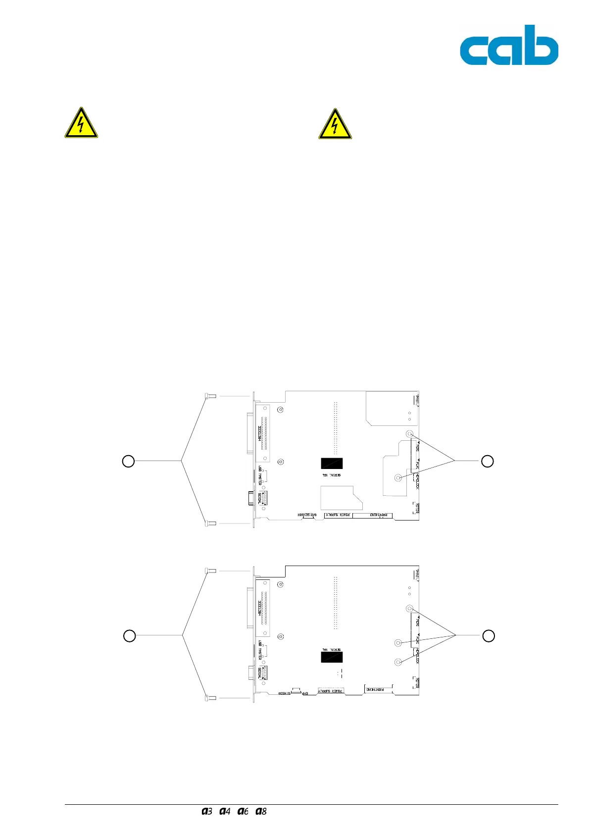
7. Beim A3 entfernen Sie die vier Schrauben (1) der
Leiterplattenbefestigung.
Bei A4, A6, A8 entfernen Sie die fünf Schrauben (2)
der Leiterplattenbefestigung.
8. Schwenken Sie die Leiterplatte CPU um 90° nach
unten und lösen Sie die unteren Steckverbinder ab.
Damit ist die Leiterplatte CPU demontiert.
4.7 Replacing the PCB CPU
Danger to life and limb!
Disconnect the printer from the mains
connection, otherwise there is a risk to life
and limb from the live wires inside the open
printer.
1. If possible backup the settings of the printer
configuration on a CompactFlash card as described in
chapter "Save NVRAM".
2. Disconnect the printer from the mains connection.
3. Pull out all interface connectors at the rear of the
printer.
4. Remove a possibly installed interface card (Ethernet,
USB Slave, Twinax-/Coax Converter, RS-422/485).
5. Remove the rear cover of the printer.
6. Pull out all plugs on the side of the PCB CPU (those
plugged into the underside can be removed more
easily when the PCB has been swivelled out).
7. For A3 remove the four screws (1) holding the PCB.
For A4, A6, A8 remove the five screws (2) holding the
PCB.
8. Swivel the PCB CPU down through 90° and remove
the plugs from the underside. The PCB CPU is now
dismounted.
Bild 29 Demontage der Leiterplatte CPU beim A3 Fig. 29 Dismounting the PCB CPU of the A3
1 1
Bild 30 Demontage der Leiterplatte CPU bei A4, A6, A8 Fig. 30 Dismounting the PCB CPU of the A4, A6 and A8
2 2
 Loading...