8
Programming
Programming the Module
This section describes programming guidelines, how to get
the module into program mode and set receiver options,
zone banks, supervision windows, and program transmitters
into memory.
Programming Guidelines
❑ NX-4 and NX-6 control panels can have receivers
added with zones that overlap those contained in the
control panel. No hardwire expanders can be used.
❑ NX-8 control panels may have expansion zones (hard-
wire or wireless) set the same as those contained in the
control panel. To do this you must disable the onboard
control panel zones. All zone expansion modules must
not overlap any blocks of 8 zones.
❑ All other control panels can have wireless zones added
to any zone. If a hardwire input (on either the control
panel or hardwire expander) is also present on the same
zone as an enabled wireless zone, the wireless transmit-
ter takes priority.
To program the module:
1. Enter [✻] [8] at the keypad. The five function lights
should start flashing.
2. Enter the “Go To Program Code” (factory default is 9 7
1 3). The service light should flash and the five func-
tion lights should change from flashing to on steady.
3. Enter [XX] [#], where [XX] is the DIP switch setting
module number and [#] is the entry key. The Armed
LED should turn on, indicating the control panel is
waiting for a programming location entry.
4. For new installations, enter [9] [1] [0] [#] to load fac-
tory defaults and clear any unwanted information in
memory before any further programming.
5. For new installations, set the receiver zone bank (Loca-
tion 194) to determine the starting zone number for the
specific receiver module. This must be set before learn-
ing sensors. The bank setting is based on the zone capa-
bilities of both the receiver and the panel.
6. Enter [0] [#] to enter the sensor learning location. The
Ready LED should turn on and the Armed LED should
turn off.
193
Receiver
Options (All
default off)
1 - Enable jam detect ❏
2 - Enable auto
advance to next
zone number ❏
3 - Keyfob user ID ❏
(off = all keyfobs
report as user 99;
on = keyfob reports
as learned zone #)
4 - Enable antenna
tamper (Only
selectable on Inter-
national versions;
reports as box
tamper) ❏
5 - Enable case
tamper ❏
6-8 Not used
None
194
Receiver
Zone Bank
Setting
(Default =
0—set this
before learn-
ing any sen-
sors. See step
5 under “To
program the
module.”)
Starting zone numbers
by bank setting:
0 = 1 ❏
1 = 9 ❏
2 = 17 ❏
3 = 25 ❏
4 = 33 ❏
5 = 41 ❏
6 = 49 ❏
7 = 57 ❏
8 = 65 ❏
9 = 73 ❏
10 = 81 ❏
11 = 89 ❏
12 = 97 ❏
13 = 105 ❏
14 = 113 ❏
15 = 121 ❏
16 = 129 ❏
17 = 137 ❏
18 = 145 ❏
19 = 153 ❏
20 = 161 ❏
21 = 169 ❏
22 = 177 ❏
23 = 185 ❏
195
Supervision
Windows
1 - Normal ______hrs.
(0 - 255 hours;
default = 24 hours)
Fire ______hrs.
(0 - 255 hours;
default = 4 hours)
(Do not change Seg-
ment 3 setting unless
required. See step 9
under “Changing the
Transmitter Supervi-
sion Windows.”)
Segment 3
Transmitter Check-
in Window ____min
(1 - 30 minutes,
default = 40—dis-
abled)
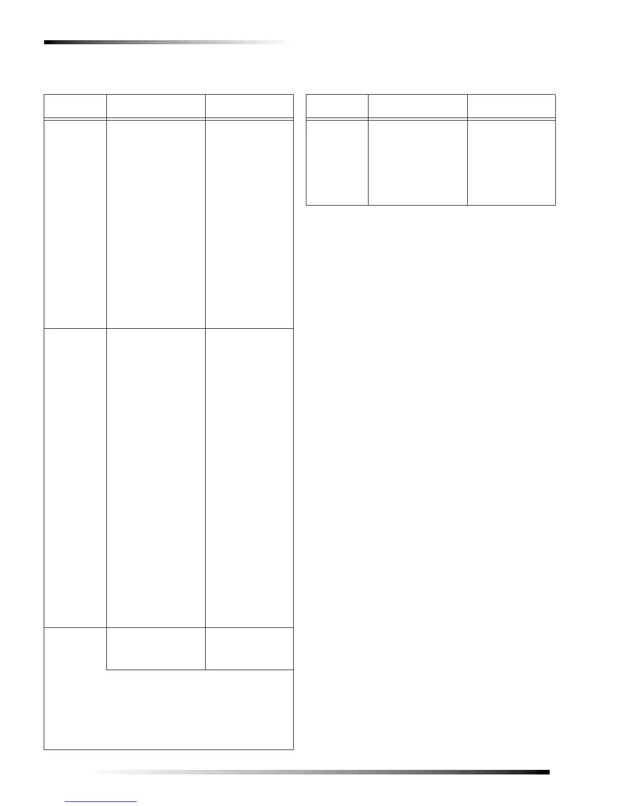
Table 3. Module Programming Settings
(Continued)
Location Segment 1 Segment 2
200
Number of
rounds
received
from last
transmitter
learned
None None
Table 3. Module Programming Settings
(Continued)
Location Segment 1 Segment 2