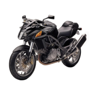
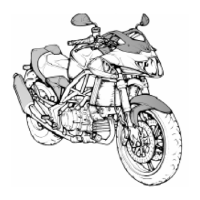
Do you have a question about the Cagiva 900 ie and is the answer not in the manual?
Safety guidelines for the operator and nearby personnel, highlighting potential hazards.
Practical advice for preventing issues and achieving optimal repair results.
Standard procedures and guidelines for performing motorcycle repairs.
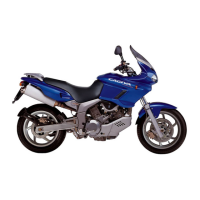
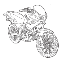
Technical specifications and general information about the engine.
Details on the valve timing system and its components.
Overview of the integrated electronic fuel injection and ignition system.
Specifications and descriptions of the front and rear braking systems.
Information on the motorcycle's frame structure and geometry.
Details on the front and rear suspension systems.
Specifications for the front and rear wheels and rims.
Overview of the motorcycle's electrical system components.
Key performance metrics of the motorcycle.
Physical dimensions of the motorcycle.
Specifications for the motorcycle's weight in various configurations.
Recommended fluids and capacities for the motorcycle.
List of components for the electronic injection and ignition system.
Description of the motorcycle's fuel supply circuit.
Details and function of the electric fuel pump.
Information on the fuel injector and its operation.
Function and specifications of the fuel pressure regulator.
Description of the air intake system and its components.
Details on the absolute pressure sensor and its function.
Information on air and coolant temperature sensors.
Details on the I.A.W. electronic control unit and its inputs.
Description of the ignition coil and power module.
Function of the throttle position sensor.
Information on the engine and camshaft pick-up sensors.
Overview of the system's operating modes.
Procedure for starting the engine with the injection system.
How the system manages fuel delivery during acceleration and deceleration.
Guide on how to connect and operate the diagnostic tool.
Interpretation of the check lamp signals and associated error codes.
Procedure for checking the engine oil level.
Instructions for replacing the engine oil and oil filter cartridge.
Procedure for checking and adjusting valve clearances.
Guidelines for checking and adjusting timing belt tension.
Procedure for adjusting the engine's idle speed.
Adjusting the starter and throttle control cables.
Adjusting the clutch and front brake control levers.
Adjusting the rear brake pedal position.
Procedure for adjusting the drive chain tension.
Procedure for adjusting the steering bearing clearance.
Instructions for adjusting the rear shock absorber settings.
Instructions for removing the seat and side panels.
Procedure for removing the motorcycle's fairing.
Steps to remove the engine guard.
Procedure for removing the fuel tank and associated system.
Instructions for removing the exhaust system.
Procedure for removing the rear frame section.
Steps to remove the air filter box and oil vapor separator.
Procedure for removing the throttle body assembly.
Instructions for removing the rear brake pump and clutch components.
Procedure for removing the engine oil cooling circuit.
Steps for removing the transmission chain.
Procedure for removing accessories from the frame cradle.
Instructions for removing the engine assembly.
Procedure for removing the left side engine cover.
Steps to remove the camshaft support cap.
Procedure for removing timing system belts and pulleys.
Steps for removing the cylinder head.
Information on cylinder and piston removal.
Procedure for removing the left side engine cover.
Steps for removing the water pump rotor and stator.
Procedure for removing the alternator rotor.
Steps for removing the electronic ignition flywheel.
Procedure for removing the timing system gear.
Steps for removing the starting device idling gear.
Procedure for removing the starter motor.
Steps for removing the drive chain sprocket.
Procedure for removing the gear shift level-system.
Steps for removing the right side engine cover.
Procedure for removing the clutch assembly.
Steps for removing the oil pump.
Procedure for removing the transmission gear.
Steps for separating the crankcase halves.
Procedure for removing the oil pressure adjustment valve.
Steps for removing the camshaft control mechanism.
Procedure for removing the driving shafts.
Steps for removing the fork guide shafts.
Procedure for removing the selector drum.
Steps for removing gear engagement mechanisms.
Procedure for removing the gearbox transmission shaft.
Steps for removing the gearbox driven shaft.
Procedure for removing the valve covers.
Steps for removing the upper rocker arms.
Procedure for removing the valves.
Steps for removing the camshaft.
Procedure for removing the lower rocker arms.
General guidelines for reassembling engine components.
Procedure for reassembling cylinder head components.
Steps for closing the crankcase halves.
Procedure for reassembling the timing system pulleys.
Steps for reassembling the transmission gear and oil pump.
Procedure for reassembling the clutch.
Steps for reassembling the gear shift level-system.
Procedure for reassembling the timing system gear.
Steps for reassembling the flywheel.
Procedure for reassembling water pump components.
Steps for reassembling the revolution number sensor.
Procedure for reassembling cylinder, piston, and head assemblies.
Steps for adjusting the timing system pulleys phase.
Details on the front suspension system.
Specifications for the front wheel and rim.
Procedure for removing the front wheel assembly.
Instructions for overhauling the front wheel hub bearings.
Procedure for overhauling the wheel rim.
Checking and correcting rim alignment for front and rear wheels.
Checking for wheel rim axle bending.
Instructions for checking and adjusting spoke nipples.
Procedure for replacing fork oil with the fork mounted.
Steps for disassembling and overhauling the front fork.
Details on the rear suspension system.
Specifications for the rear wheel and rim.
Procedure for removing the rear wheel assembly.
Information on the rear sprocket.
Steps for disassembling and overhauling the floating rear fork.
Procedure for overhauling the swinging arm pivot pin.
Instructions for overhauling connecting rod and rear suspension tie rod.
Procedure for removing the rear shock absorber.
Information on the rear shock absorber.
Overview of the motorcycle's braking system components.
Specifications and checks for the brake discs.
Procedure for checking the wear on the brake pads.
Instructions for overhauling the brake caliper.
Procedure for bleeding the motorcycle's braking system.
Instructions for overhauling the brake fluid pump.
Schematic diagram of the motorcycle's electrical system.
Explanation of symbols and components in the wiring diagram.
List of wire colours used in the electrical system.
Diagram of the ignition and fuel injection system.
Details on the ignition coil and power module.
Information on the throttle position sensor.
Details on the engine and camshaft pick-up sensors.
Overview of the system's operational phases.
Procedure for engine start-up within the electric system.
System operation during acceleration and deceleration phases.
Guide for using the diagnostic instrument.
Interpretation of check lamp signals from the diagnostic system.
Instructions for installing and preparing a new battery.
Details on the engine's generator (alternator).
Information on the regulator-rectifier unit.
Details on the starter motor's operation and installation.
Information on spark plugs and electrode gap.
Procedure to check resistance of ignition system components.
Details on the motorcycle's lighting system.
Overview of the hydraulic clutch system.
Procedure for draining the hydraulic system fluid.
Instructions for overhauling the clutch control pump.
Procedure for bleeding the hydraulic system.
Tool for locking the clutch drum.
Tool for extracting rocker arm pins.
Tool for measuring and adjusting timing belt tension.
Tool for locking cylinder head nuts.
Tool for locking alternator retaining nuts.
Tool for locking driving shaft gear retaining nuts.
Tool for assembling closing rocker arm springs.
A graduated disc component.
Tool for checking disc advance using a graduated disc.
Tool for removing connector pins.
Tool for retaining timing system pulley ring nuts.
Tool for removing chain alternator cover.
Tool for assembling rocker arms.
Tool for retaining timing system pulleys.
Tool for checking lower valve adjuster clearance.
Tool for checking lower valve adjuster clearance.
Tool for removing oil filter cartridges.
Tool for adjusting the oil carburetor.
Torque setting for the first approach of head nuts.
Torque setting for the second approach of head nuts.
Final torque setting for head nuts.
Torque setting for connecting rod screws.
Torque setting for the crank shaft gear nut.
Torque setting for the alternator rotor nut.
Torque setting for the clutch drum nut.
Torque setting for the transmission shaft gear nut.
Torque setting for the timing pulley ring nut on transmission.
Torque setting for the timing pulleys ring nut on the head.
Torque setting for the oil pump gear nut.
Torque setting for the ignition spark plug.
Torque setting for the gearbox drum screw.
Torque setting for the clutch cap screw.
Torque setting for the inlet manifold nut.
Torque setting for the exhaust bracket nut.
Torque setting for the alternator fairlead ring nut.
Torque setting for the flywheel bracket screw.
Torque setting for the transmission bearings plate screw.
Torque setting for the by-pass plug.
Torque setting for the ignition cable plug.
Torque setting for head stud bolts.
Torque setting for inlet/exhaust bracket studs.
Torque setting for the oil filter nipple.
Torque setting for the oil drain plug.
Torque setting for the idle warning light switch.
Torque setting for the gauze filter pipe plug.
Torque setting for the net oil filter.
Torque setting for the cartridge oil filter.
Torque setting for the breather cap.
Torque setting for alternator stator fastening screws.
Torque setting for the oil pump pipe plug.
Torque setting for starting gear pin screws.
Torque setting for oil pump screws.
Torque setting for ignition sensor screws.
Torque setting for the pressure switch.
Torque setting for radiator nipples.
| Displacement | 904 cc |
|---|---|
| Bore x Stroke | 92.0 mm x 68.0 mm |
| Compression Ratio | 9.2:1 |
| Fuel System | Electronic fuel injection |
| Ignition | Electronic |
| Transmission | 6-speed |
| Final Drive | Chain |
| Frame | Tubular steel trellis |
| Front Tire | 120/70 ZR17 |
| Rear Tire | 180/55 ZR17 |
| Width | 800 mm |
| Seat Height | 810 mm |
| Engine Type | 4-stroke, 90° V-twin |
| Front Suspension | Telescopic fork |
| Rear Suspension | Monoshock |
| Front Brakes | Dual 320 mm discs |
| Length | 2100 mm |
| Rear Brakes | Single 240 mm disc |