On!the!potentiometer!end,!we!would!like!to!connect!two!cables!(positive/hot!and!
ground).! The! positive/hot! cable! is! connected! to! Pin! 2! (audio! out)! of! the!
potentiometer! an d! the! ground! goes! to! Pin! 1! of! the! potentiometer! (currently!
already! being! soldered! with! the! single! core! copper! cable).! Again,! refer!
specifically! to! Figure! 25! -! Single! core! insulated! copper! w ire! used! for! ground!
connections!to!see!an!example!of!how!this!is!done.!!
!
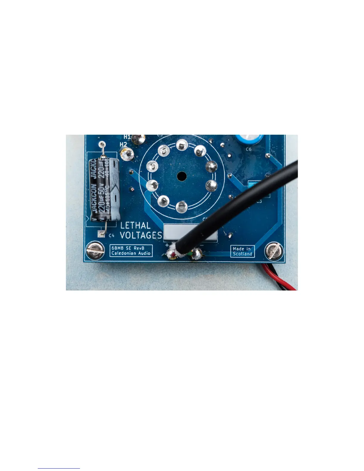
In!the!image,!you! can! see!two!sets! of! red!and!green!cables,! where!each!pair!is!
encapsulated! in! the! thick! black-sleeved! cable.! These! black! cables! are! then!
connected!to!the!amplifier!boards!at!the!“Audio!In!+!and!–“!terminals.!See!Figure!
28!-!Audio!input!cables!going!into!the!amplifier!board.!
!
!
H9Q,<#(4/(@(!,M9=(9+O,?(N*%&#"(Q=9+Q(9+?=(?P#(*$O&9L9#<(%=*<M(