20
A
A
Periodic maintenance
Maintenance
All maintenance procedures should be carried out by an authorised technician. Regular
maintenance guarantees better efficiency and helps to save energy. Before carrying out any
maintenance, repair or part replacement work, proceed as follows:
- Cut off the electric supply
- Remove the cover
- Close the shut-off valves
- Empty the heat interface unit using the drain cocks provided.
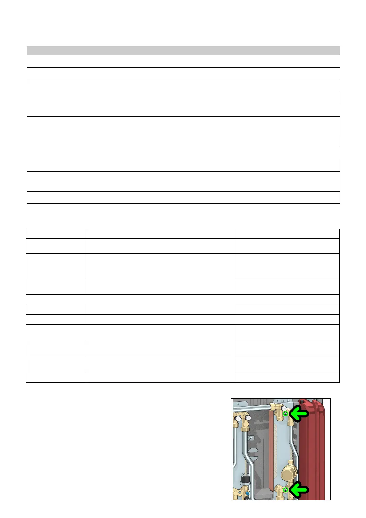
Exchanger replacement
- As a preliminary step, remove the flow sensor (refer to “replacing the DHW priority flow
meter”, on page 21) and position it where it cannot be reached by any dripping liquid.
- Remove the exchanger, loosening the 2 hex socket head screws fixing it in place (A)
- Replace the exchanger and the O-rings.
- Tighten the two fixing screws (A) after having checked that the O-rings are correctly
positioned. Tightening torque 3-3,5 Nm.
N.B. Make sure to respect the correct orientation of the plate heat exchanger when fitting it back.
O
PERATIONS TO BE PERFORMED
Force an actuators reset by switching the HIU power supply OFF and then ON
Visually check for the absence of leaks and/or anomalies
Check for possible active errors shown on the user interface
Test correct operation of the pump by closing the thermostat contact or forcing it to close
Clean the strainers: on the primary flow line (component 17, page 4), on the secondary return line (19), upstream of the domestic water flow meter
(22)
After having isolated the HIU by means of shut-off valves, discharge the pressure in the secondary circuit and make sure the expansion vessel pre-
charge value is between 0.9 and 1.2 bar. Restore the pressure value, if necessary
Re-open the shut-off valves and restore secondary circuit pressure to a value between 1.3 and 1.7 bar
Check for the absence of any liquid dripping from the safety relief valve and ensure the drain is unobstructed
Check for the absence of internal leakage through the modulating valves when none of the services are active
Check correct setting of the set points (DHW and heating). Unless explicitly requested by the user or for normative reasons, a DHW temperature
set point of 50°C or lower is recommended
With the primary circuit at working temperature, check that the DHW flow rate at the correct temperature is sufficient
The following checks must be carried out at least once very 12 months, in accordance with the prescriptions of standard EN 806-5.
Summary of the technical parameters
Here follows a summary of the meaning and possible settings of the technical parameters:
Parameter Meaning Settings
t00 Temperature range of the HIU
0 = 45 - 75°C
1= 25 - 45°C
t01 Heating flow temperature control
0 = fixed set point
1 = fixed set point with RTL
2 = compensated on return temperature
3 = weather compensated
t02 DHW comfort mode
From 0 = pre-heating of the heat exchanger
1 = DHW recirculation
t03 Maximum % opening of the heating modulating valve From 50 to 100
t04 Maximum % opening of the DHW modulating valve From 50 to 100
t05 Configuration of the closing logic of the auxilliary microswitch See page 16
t06 DHW temperature control
0 = fixed set point
1 = fixed set point with RTL
t07 Freezing of some settings
0 = All temperature settings can be modified
1 = Return temperature limits are freezed
t08 Anti-legionella
0 = disabled
1 = enabled between 3:00 to 3:30 a.m.
t09 Duration of a DHW recirculation cycle 1 unit = 10 seconds
 Loading...