4
3
9
4
7
10
8
5
2
1
20
11
14
19
1
8
17
13
1
2
22
2
3
24
16
27
25
26
21
6
15
29
28
T
S
P
TA
2
V
V
V
V
V
V
3 4
5
6
7
8
9
10
11
12
13
14
15
18
17
16
20
19
23
24
25
26
27
28
29
21
22
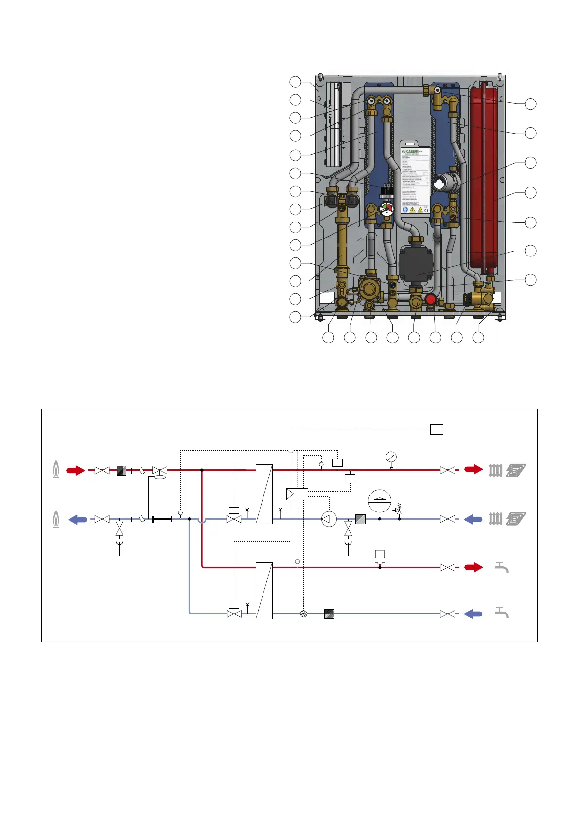
1. Frame
2. Controller
3. Heating exchanger primary circuit air venting/drain
4. Heating exchanger secondary circuit air venting/drain
5. Heating exchanger
6. Pressure switch
7. 2-way modulating valve - Heating
8. 2-way modulating valve - DHW
9. Return temperature probe
10. Pressure gauge
11. Safety thermostat
12. 130 mm heat meter template
13. 1/4” F pressure test port
14. Connection for M10x1 heat meter return probe
15. Primary drain cock
16. Connection for M10x1 heat meter flow probe
17. Mesh strainer + 1/4” F pressure test port
18. Differential pressure regulating valve
19. Secondary drain cock + mesh strainer
20. Safety relief valve
21. Flow meter (turbine + sensor)
22. Mesh strainer
23. Heating flow temperature probe
24. Pump
25. DHW temperature probe
26. Expansion vessel
27. Water hammer arrester
28. DHW exchanger
29. DHW exchanger primary circuit air venting/drain
Characteristic components
Hydraulic diagram
 Loading...