GB
BS...IMAT Rev2 - Operating Instructions Page 5 / 12
Adequate drainage should be provided with
protection from water damage in the immediate
vicinity should a leak or spillage occur.
Adequate lighting should be provided for service,
inspection and commissioning.
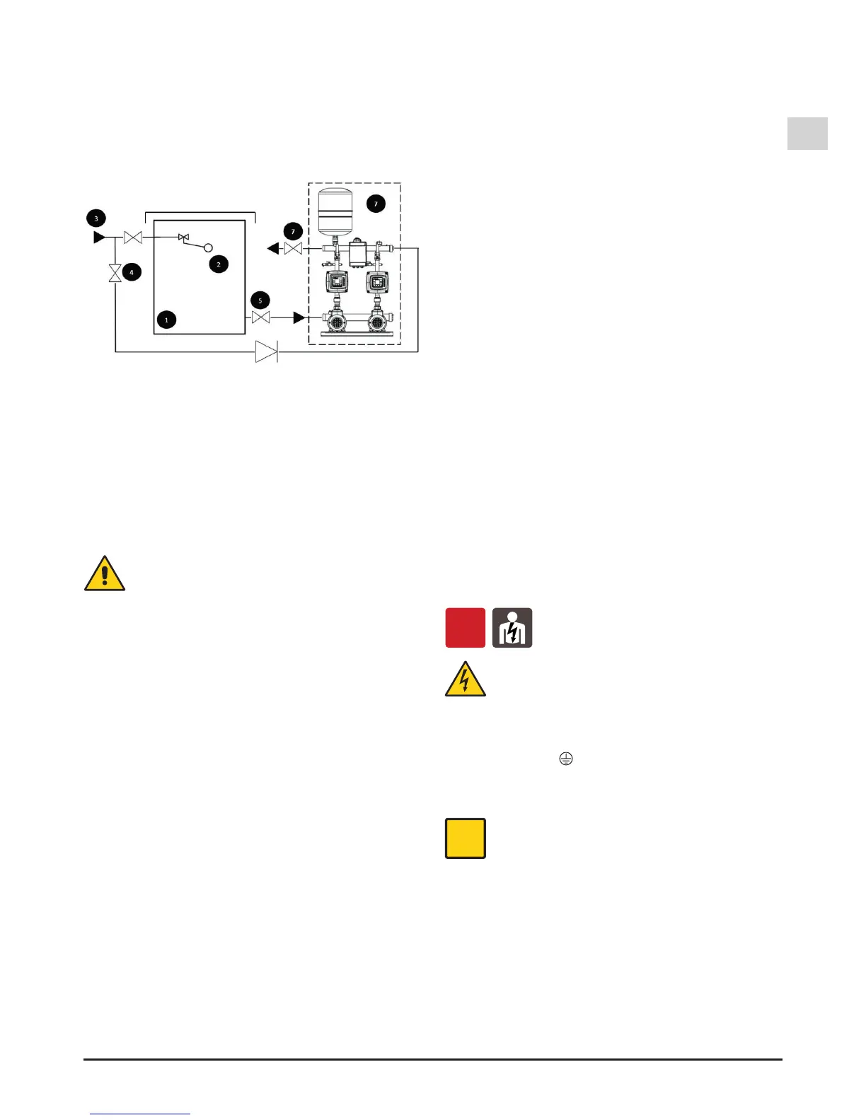
6.3.1. General arrangement
It is important that the following items are installed
over and above those supplied with the standard
booster set:
1. Storage tank.
2. Ball/Float valve.
3. Mains Water inlet.
4. Mains Water by-pass
5. Suction Isolating valve.
6. Discharge Isolating valve.
7. Booster set.
Installation must be in accordance with local
regulations and Water bye-laws.
6.3.2. Foundation
The set should be installed with anti-vibration
mounting pads and anti-vibration pipe coupling
especially
in noise sensitive areas. Otherwise install the set
on a level concrete plinth which will not distort or
twist
the base-plate, use shims if required. Always install
in a horizontal position and use adequate xings.
Do
not install on a wooden substructure or any
potentially exible substructure.
6.3.3. Storage tank and bypass
The booster sets must be used in conjunction with
an adequately sized water storage tank, supplied
and installed in accordance with the water byelaws.
The set must not be directly connected to a mains
water
supply. In the event of a failure of the booster set
it is advised that a cold water mains bypass should
be tted to allow for a continued supply even at a
reduced pressure. The bypass should be installed
in-line with water byelaws.
6.4. Pipes
Ensure the insides of pipes are clean and
unobstructed before connection.
ATTENTION: The pipes connected to the booster
set should be secured to rest clamps so that they
do not transmit stress, strain or vibrations to the
booster set.
The pipe diameters must not be smaller than the
booster set connections.
Isolation valves should be tted before the set
suction manifold and on the discharge manifold
after the set to allow the set to be removed without
a major loss of water in the system.
6.4.1. Suction pipe
The suction pipe must be perfectly airtight and be
led
upwards in order to avoid air pockets.
With a booster set located above the water level
(suction lift operation) t a foot valve with strainer
which must always remain immersed.
With the liquid level on the suction side above the
pump (inow under positive suction head) t an
inlet gate valve.
For suction from a storage tank t an anti-backow
valve.
Follow local specications if increasing network
pressure.
6.4.2. Delivery pipe
Fit a gate valve in the delivery pipe.
6.5. Electrical connection
OFF
Electrical connection must be carried out
only by a qualied electrician in accordance
with local regulations.
Follow all safety standards.
The unit must be properly earthed (grounded).
Connect the earthing (grounding) conductor to the
terminal with the
marking.
Compare the frequency and mains voltage with
the plate data and connect the in accordance with
the diagrams.
The set is supplied with a separate control
box which allows control and monitoring
features to be connected without accessing
either the motor terminal box or the inverter
terminals. Please follow carefully the wiring
diagrams supplied.
6.6. Power supply connection
Electrical supply must comply with the description
in section 3.
If the electric control box is connected to an
electric plant with a differential switch (ELCB) or
a Ground Fault Circuit Interrupter (GFCI) as a
further protection, these devices must comply the