S-Series Technical Manual 69 Cambridge Engineering, Inc.
ELECTRONIC DISCHARGE-SPACE
MODULATION/HAZARDOUS AREA
The Hazardous Area temperature control system func-
tions identical the EDSM/TP, except the space sensor
(TS244A) is replaced by a space sensor with epoxy
coated circuitry (ES225A). The standard remote control
station is not suitable for hazardous areas and would need
to be mounted outside of the hazardous area.
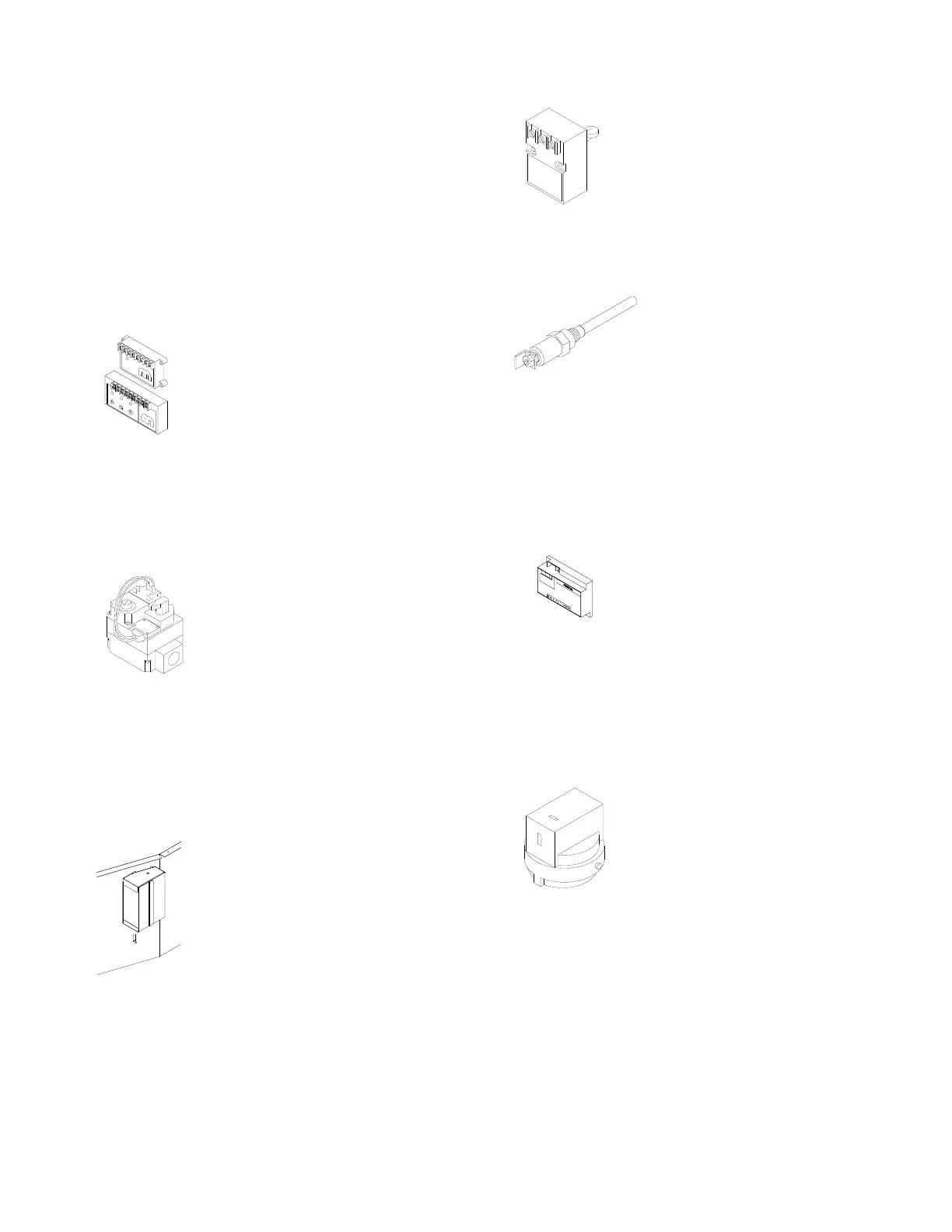
GAS CONTROL COMPONENTS
AMPLIFIER (AMP)
The amplifier creates a voltage output
to drive the modulating valve to main-
tain the selected discharge tempera-
ture. On EDL control systems, the dis-
charge temperature is set at the ampli-
fier. On EDR control systems, the dis-
charge temperature is set on the RHA.
On EDSM control systems, the range of the discharge
temperature is set at the amplifier, however, the STS
controls when more or less heat is required.
COMBINATION VALVE
The combination valve serves as a
manifold pressure regulator and
redundant gas shut-off valve. This
control is typically used for gas
capacities below 400,000 Btu/hr. The
valve operates on 24 Volts AC power.
The combination valve is rated for a maximum gas
supply pressure of 14" WC.
DISCHARGE AIR TEMPERATURE
SAMPLING BOX
The discharge air temperature sam-
pling box is located on the side
of the discharge, and is accessible
from the electrical control enclosure
side of the unit. The sampling box
houses the high limit (HL) and the
discharge temperature sensor (DTS).
This box should not be tampered with
unless performing the Calibration
Procedures (pages 29-31).
DISCHARGE TEMPERATURE SENSOR
(DTS)
The DTS is mounted in the discharge of
the heater. It senses the average dis-
charge temperature and transmits a
resistance signal back to the amplifier
that corresponds to the discharge tem-
perature.
FLAME ROD (FR)
The flame rod senses the presence
of flame and signals the flame
safeguard relay. The presence of
flame is detected by the flame
rectification of the AC signal that
is supplied to the flame rod thus
creating the DC response. The resulting current flow
produced can be measured with a DC microammeter.
The reading should be steady and between 2.0 and 6.0
microamps (mA).
FLAME SAFEGUARD RELAY (FSR)
The flame safeguard relay supplies 24
Volts AC to the igniter for 4 seconds
before the gas valve is energized. If the
burner does not light (flame is not
established within 7 seconds), this con-
trol will lock out gas flow until the control is reset. If
flame signal is lost during burner operation, the control
will allow one retry for ignition.
HIGH/LOW GAS PRESSURE SWITCH
(HGP, LGP)
This gas pressure switch is a manual
reset safety device to lock out the
burner operation should large gas pres-
sure fluctuations occur. The high gas
pressure switch should be set 3" WC
above manifold gas pressure. The low
pressure switch should be set at 2"
WC. The adjustment screw is located under the top
plate. The low gas pressure switch will have to be reset
whenever gas supply has been interrupted.