Cambridge Engineering, Inc. 70 S-Series Technical Manual
HIGH PRESSURE REGULATOR (HPR)
The HPR option is required when the
gas supply pressure exceeds the
nameplate rating for the heater.
Unless otherwise specified, the HPR
assembly is also furnished with a high
gas pressure manual shut-off valve
and a tap for measuring the upstream gas pressure. The
HPR must be a positive lock-up type regulator which
must be vented to outdoors. It is sized according to the
gas supply pressure and the capacity requirements of
the heater.
INTERMITTENT/CONTINUOUS CONTROL
The Intermittent/Continuous Control allows the burner
input to be modulated to be operated continuously at
modulating discharge temperature for make-up air (see
EDSM on page 68) or operated intermittently based on
a thermostat at maximum discharge temperature (see
EDL on page 68) for space heating.
Requires EDSM controls and a signal to switch
between modes (Exhaust Fan Interlock, Temperature
Setback System, Manual Make-Up Air Switch, etc.)
IGNITER (IG)
The hot surface igniter is the igni-
tion source for lighting the gas in
the burner. It is made of silicon car-
bide which is very fragile. Care
should be used in handling. It oper-
ates on 24 Volts and the current
ranges from 1.3 to 1.7 amps. It will reach temperatures
in excess of 2400˚F during the ignition trial. It is fur-
nished with a vinyl sleeve for shock mounting and
sealing in the mounting tube.
LEAK TEST FACILITY (SW4)
The leak test facility is provided on
all heaters over 400,000 Btu/hr. It
consists of a momentary switch for
the shut-off valve (SOV) in the gas
train and a gauge port between the
(SOV) and (SSV) shut-off
valve. By holding the gas valve
momentary switch closed, the (SOV)
gas valve is energized which allows
gas pressure to build on the seat of
the SSV safety shut-off gas valve.
The gauge port between valves is used to determine if
the SOV shut-off gas valve seat is properly sealed.
MANIFOLD PRESSURE REGULATOR
The manifold pressure regulator con-
trols the burner manifold pressure.
When the MR212 valve is used, this
modulating valve also serves as the
manifold pressure regulator. The
maximum gas supply pressure rating
is normally determined by the
exposed pressure rating of the regulating device. RV61
and RV81 regulators are rated at 1 psig; and the
MR212 is rated at 5 psig. (For units rated at 400,000
Btu/hr or below, see the combination valve below.)
MODULATING VALVE (MV)
The MV responds to a 4 to 24 Volt
DC signal from the amplifier to
modulate the flow of gas to the
burner. On the M511 or M611
valve, the low fire adjusting screw is
located on the far side of the valve
under the dust cover. On the MR212 valve, the low fire
adjusting screw is located under the large dust cover.
The MR212 modulating valve also serves as the mani-
fold pressure regulator.
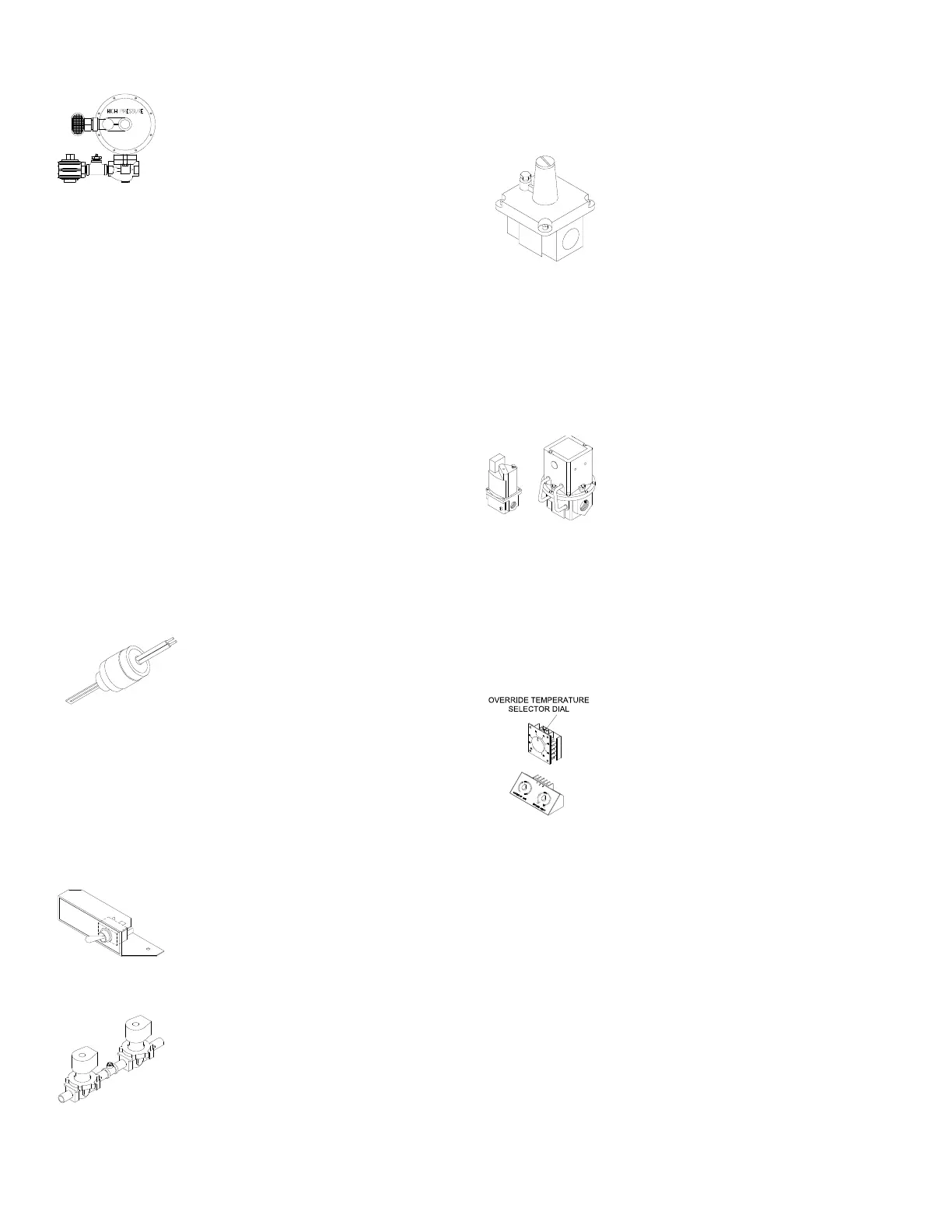
REMOTE HEAT ADJUSTMENT (RHA)
As discussed under the component
description for the EDR control sys-
tem, the RHA may have a single or
dual adjusting knob(s) on the dial
face. The single adjusting knob con-
trol permits manual adjustment of
the discharge air temperature from
55 to 130˚F. The override tempera-
ture selector dial which is visible from the top of the
RHA control, increases the discharge temperature
above the setting on the dial face by the increment
selected when a jumper or switch contact is provided
across terminals 20 and 22.
Heaters which are specified with a temperature rise
above 130˚F are supplied with dual adjusting knobs on
the dial face of the RHA. This control permits manual
adjustment of the discharge temperature from 55 to
105˚F or 120 to 160˚F. A jumper or switch contact
is required across terminals 20 and 22 to activate the
higher temperature selection.