S-Series Technical Manual 71 Cambridge Engineering, Inc.
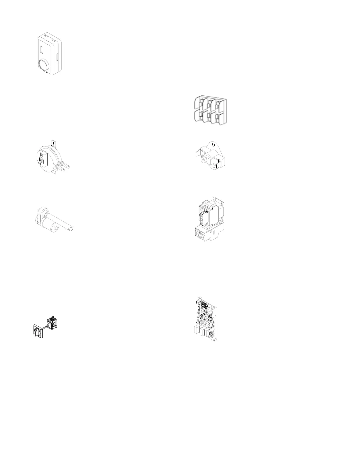
SPACE TEMPERATURE SELECTOR (STS)
The STS is part of the EDSM control
system. The STS senses the space tem-
perature and provides a resistance sig-
nal back to the amplifier that corre-
sponds to the temperature variation
from setpoint. A 3˚F drift from the set
temperature will cause the heater to
modulate to the extreme end of the preset range on the
amplifier.
HEATER COMPONENTS
AIRFLOW SWITCH (AF)
The airflow switch senses the pressure
drop across the burner. It is factory set
and not adjustable. It is designed to
prevent burner operation if the airflow
drops significantly below the minimum
design airflow of the heater.
DAMPER MOTOR (D, D1)
The damper motor operates on 24
Volts AC and switches power to the
motor starter when the damper blades
are fully open by the closure of the
damper end switch. The damper end
switch is an adjustable internal auxil-
iary switch which has been factory set to operate when
the damper is fully open. The damper motor will power
closed when the heater cycles off. The damper motor
will not close unless the blower service switch is in the
“REMOTE” position. For detailed instructions refer to
Damper Motor Replacement & Adjustment (page 54).
DISCONNECT SWITCH (DISC)
The disconnect switch is provided on all
heaters and includes the disconnect rod and
lockable operating knob. The disconnect
switch must be in the “OFF” position to
gain access to the control enclosure. Once the control
enclosure is open, experienced service technicians may
activate the electrical circuit by twisting the disconnect
rod clockwise to assist in troubleshooting. The discon-
nect rod must be turned back to the “OFF” position
before attempting to secure the enclosure door.
EXHAUST FAN CONTACT (EFC)
The exhaust fan contact is an auxiliary dry contact that
is mechanically interlocked to the heater’s motor starter
and is provided with terminals located in the electrical
enclosure. The EFC is typically wired into an exhaust
fan control circuit to activate the exhaust fan as a slave
to the heater.
FUSE BLOCK (FU1, FU2)
The fuse block provides line fusing for
branch circuit protection. It is wired in
conjunction with the non-fused discon-
nect switch.
HIGH TEMPERATURE LIMIT (HL)
The high limit opens when discharge
temperature exceeds 180˚F. This limit
must be manually reset.
MOTOR STARTER (MS, OL, AUX)
The motor starter assembly consists of
a motor starter, overload relay and
auxiliary contact. The overload relay
protects the motor from excessive cur-
rent or single phasing. If the overload
relay trips, it must be reset manually.
The auxiliary contacts are used in the
gas valve safety circuit as an indica-
tion the blower is operating, and as an optional exhaust
fan contact for interlocking other equipment with the
operation of the heater.
MULTI-FUNCTIONAL PC BOARD
The multi-functional PC board provides
five (5) separate functions as follows:
1) Blower Relay (CR1) which is energized
on “call for blower” from the remote con-
trol station.
2) The LTC (Low Temperature Cutout) circuit func-
tions to shut down the blower in approximately 3
1
/2
minutes if either of the following occurs: (a) The inlet
temperature drops below the LTC setpoint (40, 45, 50,
or 55˚F) in the ventilation mode; or (b) the gas valve
fails to remain energized during a heating cycle.
3) The EAT (Entering Air Thermostat) circuit func-
tions automatically to turn off the burner when the out-