14
Reversing the Door Swing
approximately 1 inch and pull out to remove the
trim and expose the handle mounting screw, refer
figure 3. Remove the screw using a
Phillips screwdriver.
• Remove the two screws, which hold
the handle to the top of the door.
• Remove the handle.
Safety Information
Installation Instructions
Customer ServiceOperating InstructionsTroubleshooting Tips
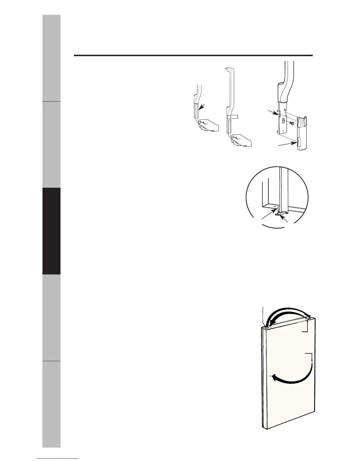
To remove handle with long trim…
The handle with long trim is secured in the same manner
as the handle with short trim but has an additional pin
to secure the long trim to the bottom of the door.
Refer figure 4.
• Remove the pin securing the bottom of the long trim
using a Phillips screwdriver.
• Grip the long trim near the bottom and slide down
approximately 1 inch and pull out near the handle to
remove the trim and expose the mounting screw, refer
figure 3. Remove the screw using a Phillips screwdriver.
• Remove the two screws, which hold the handle to the top of the door.
• Remove the handle.
After removing handle…
• Remove screws from right edge of door top and insertthem into handle screw
holes on left side.
• Remove plug button from left top edge of door and insert it
into hole on opposite side, refer figure 5.
• Transfer medallion on door to opposite side.
When reinstalling handle…
• On models with long trims, use one of the painted screws to
clear the inboard locating pin hole on the bottom door
edge by inserting and removing the screw. Refer figure 4.
• Attach the handle to the right side of door with two screws
at the top followed by the single screw in the handle tail.
• Align the trim tabs over the handle tail notches as shown
figure 3. Slide the trim until the trim fits tightly against
the handle. On models with long trims the locating pin
must also be inserted into the locating hole as indicated in
figure 4.
Fig. 2
Fig. 3
Inboard
Hole
Locating Pin
Fig. 4
Plug Button
Screws For
Handle Holes
Medallion
Fig. 5
Trim Tab
Tape
Handle Tail
Notches
1"