EasyManua.ls Logo

Cameron Demco - Disc;Pipe Clearance

Cameron Demco
11 pages
Print Icon
To Next Page IconTo Next Page
To Previous Page IconTo Previous Page
Loading...
8
TC-003001-01 / Rev 2
Valve
Size
(in)
Bolt
Circle
Dia (in)
Bolt
Size
Wafer Body
Lug Body
Qty
Stud
Length (in)
‘A’
Qty
Capscrew
Length (in)
‘B’
2
4.75
5/8-11
4
5.00
8
1.50
2-1/2
5.50
5/8-11
4
5.50
8
1.50
3
6.00
5/8-11
4
5.50
8
1.75
4
7.50
5/8-11
8
5.75
16
1.75
5
8.50
¾-10
8
6.50
16
1.75
6
9.50
¾-10
8
6.50
16
2.00
8
11.75
¾-10
8
7.00
16
2.25
10
14.25
7/8-9
12
7.50
24
2.25
12
17.00
7/8-9
12
8.25
24
2.50
14
18.75
1-8
12
8.25
24
2.50
16
21.25
1-8
16
10.00
32
3.25
18
22.75
1-1/8-7
16
10.50
32
3.50
20
25.00
1-1/8-7
20
11.75
40
4.00
24
29.50
1-1/4-7
20
12.50
40
4.00
30
36.00
1-1/4-7
*
*
56
5.00
36
42.75
1-1/2-6
**
**
***
***
* - 24 Studs 1 1/4" - 7 x 15.50" ; 8 Capscrews 1 1/4" - 7 x 5.00"
** - 28 Studs 1 1/2" - 6 x 18.50" ; 8 Capscrews 1 1/2" - 6 x 5.50"
*** - 56 Capscrews 1 1/2" - 6 x 6.00" ; 8 Capscrews 1 1/2" - 6 x 5.50"
DISC/PIPE CLEARANCE
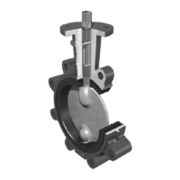
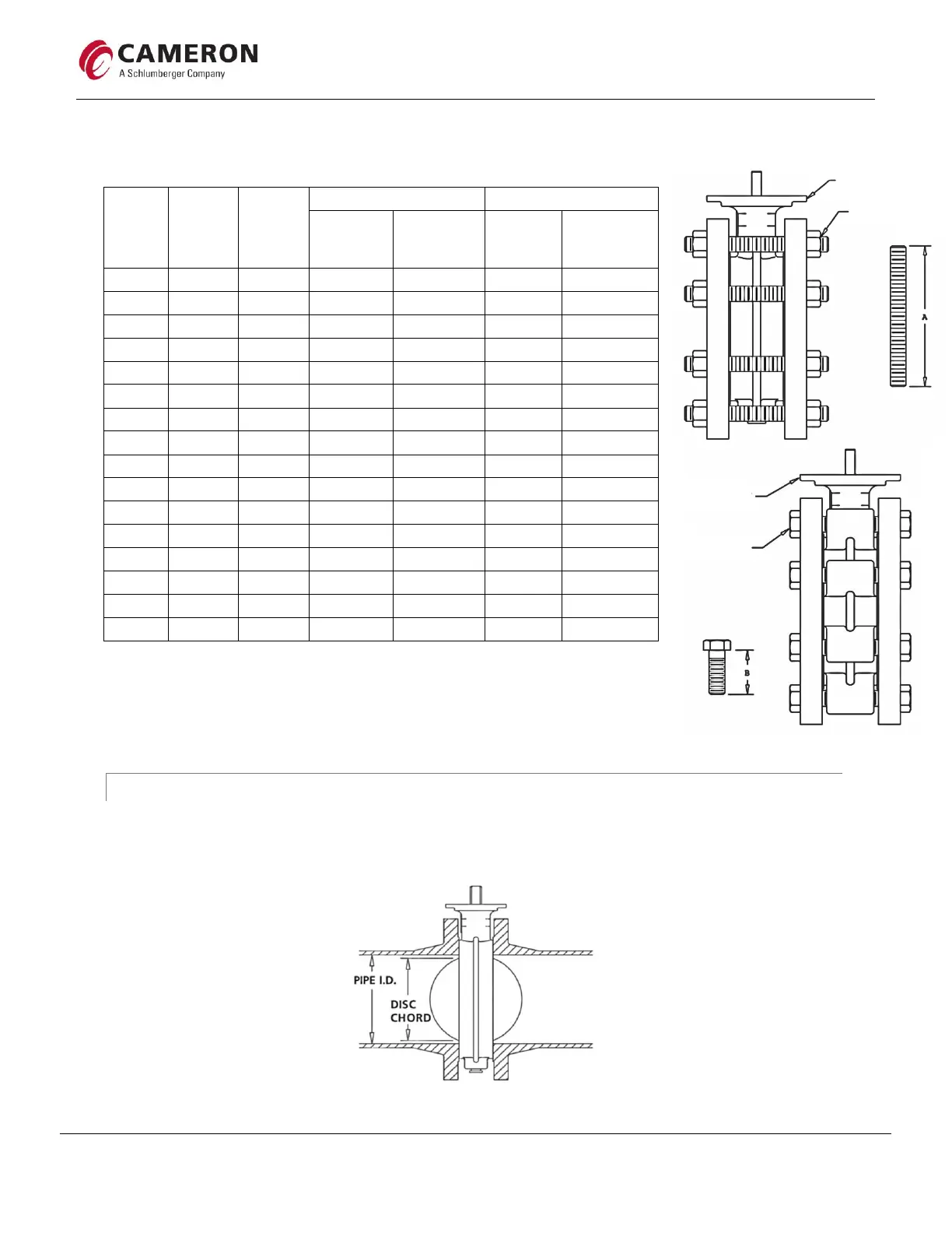
Before beginning installation, disc/pipe clearance should be checked (Figure 10) to avoid the possibility of scraping
the disc edge on the pipe ID and damaging the sealing surface. Minimum pipe ID requirements are shown below in
Table 5.
Figure 10
Table 4
B
Lug Body
Capscrew
Studs & Hex Nuts
Wafer Body
Studs & Hex Nuts
Lug Body
Capscrews

Related product manuals