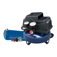
Assembly (Con't)
For 10 inch diameter wheels, feed
the shoulder bolt through the top
hole on the tank axle iron and
tightly secure with the Iocknut.
Repeat on the opposite side.
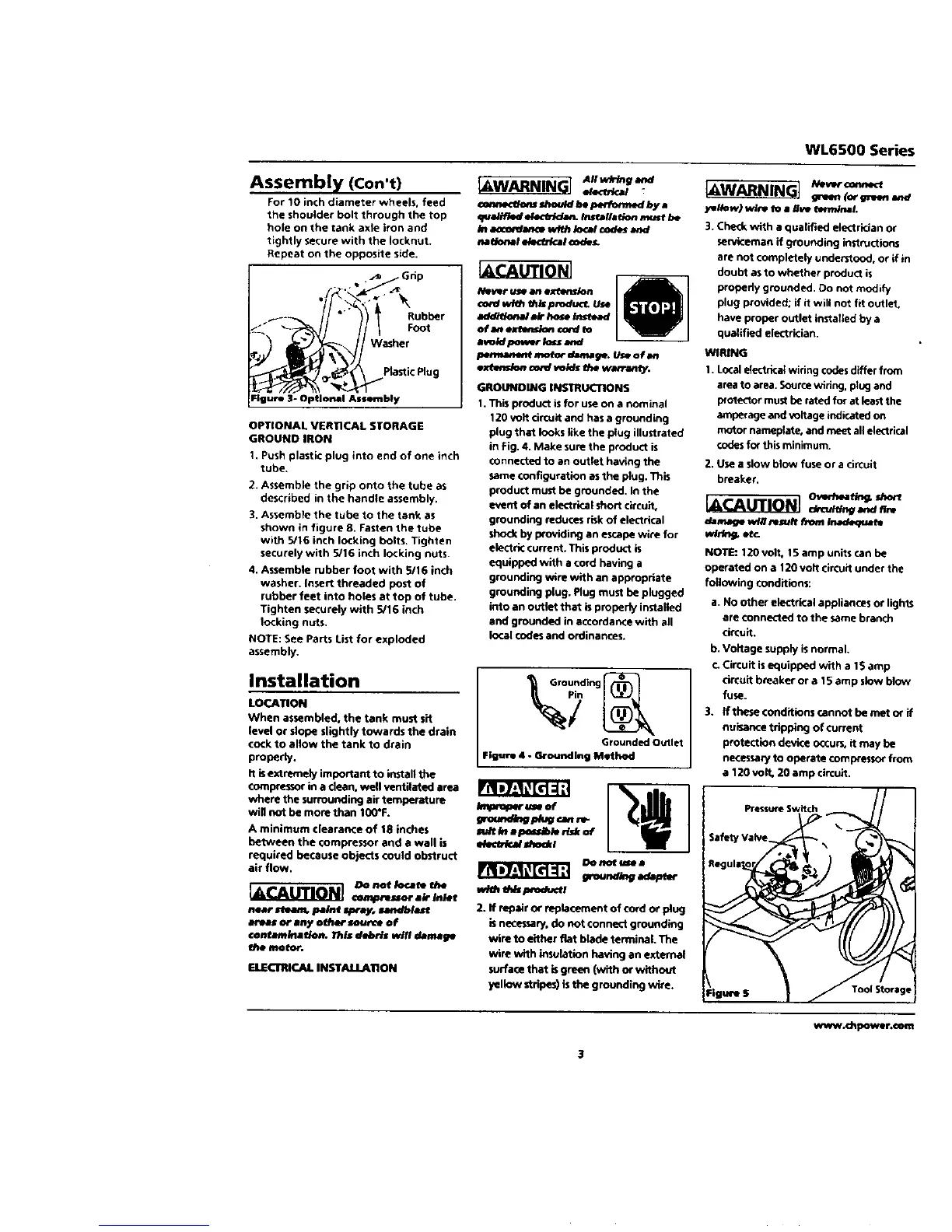
•_ Grip
Figure 3- Optlomll Assembly
OPTIONAL VERTICAL SIORAGE
GROUND IRON
1. Push plastic plug into end of one inch
tube.
2. Assemble the grip onto the tube as
described in the handle assembly.
3. Assemble the tube to the tank as
shown in figure 8. Fasten the tube
with 5/16 inch locking bolts. Tighten
securely with 5/16 inch locking nuts.
4. Assemble rubber foot with 5/16 inch
washer. Insect threaded pest of
rubber feet into holes at top of tube.
Tighten securely with 5/16 inch
locking nuts.
NOTE: See Parts List for exploded
assembly.
Installation
LOCATION
When assembled, the tank must sit
level or slope slightly towards the drain
cock to allow the tank to drain
properly,
It isextremely important to install the
compressor in a dean. well ventilated area
where the surrounding air temperature
will not be morethan t00*F.
A minimum clearance of 18 inches
between the compressor and a wall is
required because objects could obstruct
air flow.
rR=7_=lt_[d=1;
DO not/ocat_ the
near _ pa/nt spray, sandbtaurt
areas or any oth_ source of
€onMm/flab_n, This debris wilt damage
I_bemotor.
GILECTRIC_L INST,4U.ILATION
IAWARNINGI A,I-_V_R.,_
ateOWcal
€oemKl_s lhoutd bt _ by a
qu_//f_d e/ec/rida_ Insf_//ation must be
/n axx_am:e with/oca/€odes and
_l_# mc_-blcat _o_es.
GROUNDING INSTRUCTIONS
1.This product isfor use on a nominal
120 volt circuit and has a grounding
plug that looks llke the plug illustrated
in Fig. 4. Make sure the product is
connected to an Outlet having the
same COnfiguration as the plug. ThiS
product must be grounded, in the
event of an electrical short circuit,
grounding reduces risk of electrical
shod( by providing an escape wire for
electric current. This product is
equipped with a cord having a
grounding wire with an appropriate
grounding plug. Plug must be plugged
into an outlet that is properly installed
and grounded in accordance with all
local codes and ordinances.
md_kl i _*m_db/e n_k of
w/_ _p_oduct_
2.it repalror reple©ementof cordor ping
isnecessary,do not connectgrounding
wire to eitherfiat blade terminal.The
wire with insulationhavingan external
surfacethat isgreen (with or without
yellow stripes)isthe grounding wire.
WL6500 Series
_WARNINGI _.v,,o_._
IF_n (or g_Nm and
yetlow) wlre to a _ve tmmlnaL
3. Che_k with a qualified electrician or
sen*iceman if grounding instructions
are not completely understood, or if in
doubt as to whether product is
properly grounded. Do not mndify
plug provided; if it will not fit outlet.
have proper outlet installed by a
qualified electrician.
WIRING
1. Local electrka_ wiring codes differ from
area to area. Sourcewiring, plug and
p_otect_r must be rated for at least the
amperage and voltage indicated on
motor nameplate, and meet all electrical
codesfor this minimum.
2. Use a slow blow fuse or a circuit
breaker,
IACAUTION] d._ ._.re
damage wf# result fn_-n/nade<F_ fe
whig. et_
NOTE: 120 volt, 15 amp units can be
operated on a 120 volt circuit under the
following conditions:
a. No other electrical appliances or lights
are connected to the same branch
drcuit.
b. Voltage supply isnormal.
r. Circuit isequipped with a 15 amp
circuit breaker or a 15 am p slow blow
fuse.
3. ff tbese €onditions cannot be met or if
nuisance tripping of current
protection device occurs, it may be
necessar/to operate compressor from
a 120volt. 20 amp circuit.
www.d_power,c_m

 Loading...