Model 107 Temperature Probe
5
7. Installation
If you are programming your datalogger with Short Cut, skip Section 7.1,
Wiring to Datalogger
(p. 5), and Section 7.2, Datalogger Programming (p. 5).
Short Cut does this work for you. See Section 4, QuickStart
(p. 1), for a Short
Cut tutorial.
7.1 Wiring to Datalogger
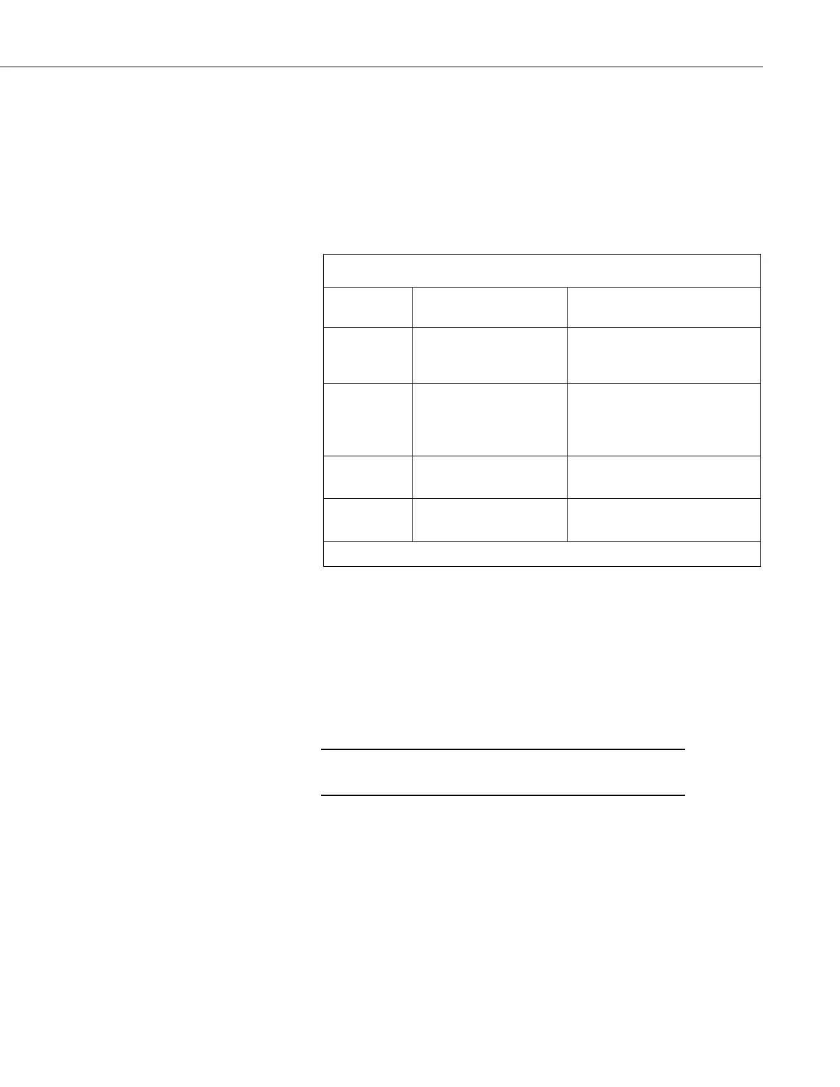
TABLE 7-1. Wire Color, Function, and Datalogger Connection
Wire Color Wire Function
Datalogger Connection
Terminal
Black Voltage-excitation input
U configured for voltage
excitation
1
, EX, VX
(voltage excitation)
Red Analog-voltage output
U configured for single-ended
analog input
1
, SE
(single-ended,
analog-voltage input)
Purple Bridge-resistor lead
(analog ground)
Clear EMF shield
(analog ground)
1
U channels are automatically configured by the measurement instruction.
7.2 Datalogger Programming
Short Cut is the best source for up-to-date datalogger programming code.
If your data acquisition requirements are simple, you can probably create and
maintain a datalogger program exclusively with Short Cut. If your data
acquisition needs are more complex, the files that Short Cut creates are a great
source for programming code to start a new program or add to an existing
custom program.
Short Cut cannot edit programs after they are imported and edited
in CRBasic Editor.
A Short Cut tutorial is available in Section 4, QuickStart (p. 1). If you wish to
import Short Cut code into CRBasic Editor to create or add to a customized
program, follow the procedure in Appendix A, Importing Short Cut Code Into
CRBasic Editor
(p. A-1). Programming basics are provided in the following
section. A complete program example can be found in Appendix B, Example
Programs
(p. B-1).
If the 107 probe is to be used with long cable lengths or in electrically noisy
environments, consider employing the measurement programming techniques
outlined in Section 8.3, Electrically Noisy Environments
(p. 9), and Section 8.4,
Long Cable Lengths
(p. 9).
 Loading...


