Model 107 Temperature Probe
8
The 107 is held in the RAD06 radiation shield by inserting the sensor through
the sensor gland at the bottom of the shield (FIGURE 7-2 right). Loosen the
nut on the gland, and insert the probe into the shield. Tighten the nut on the
sensor gland using an adjustable wrench until the sensor is securely held in
place. Route the sensor cable to the instrument enclosure.
Secure the cable to the tripod or tower using cable ties.
7.4 Water Temperature Installation
107 probes can be submerged to 15 m (50 ft) or 21 psi. The 107 is not
weighted, so a weighting system should be added, or the probe secured to a
submerged object such as a piling.
7.5 Soil Temperature Installation
The 107 tends to measure the average temperature over its length, so burying
the probe such that the measurement tip is horizontal to the soil surface at the
desired depth is usually preferred. The maximum burial depth for soil that
could become saturated with water is dictated by the maximum water pressure
allowed for the sensor, which is 21 psi.
One or two coils of cable should also be buried in a shallow installation. Burial
of some cable mitigates the effect of solar heating of the above ground cable on
the temperature measurement.
Placement of the cable inside a rugged conduit may be necessary for long cable
runs, especially in locations subject to digging, mowing, traffic, use of power
tools, or lightning strikes.
8. Operation
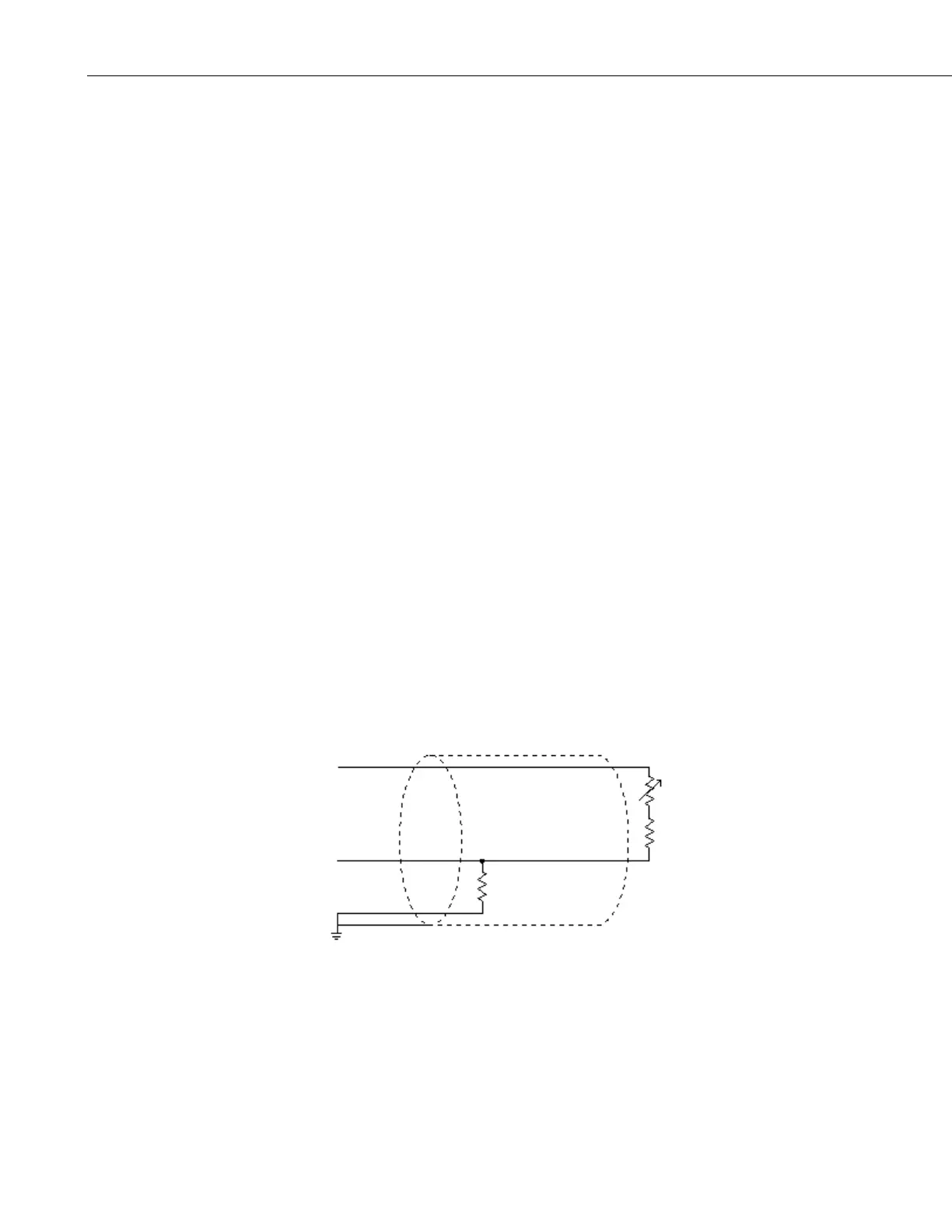
8.1 Sensor Schematic
FIGURE 8-1. 107 thermistor probe schematic
8.2 Measurement and Output Linearization
CRBasic instruction Therm107() measures the 107 probe thermistor and
automatically converts the result to temperature. With reference to the previous
FIGURE 8-1, 107 thermistor probe schematic, Therm107() applies 2000 mV
Ω, 0.1% 10 ppm
 Loading...


