Fuel Pump
1
,; Enabled
DisaPied
Activate
Fuel Pump
(Doling Fan
Acce5sory Relay
trnr2011-011 017_0
Section 04 FUEL SYSTEM
Subsection 02 (ELECTRONIC FUEL INJECTION (EFI))
4. Wrap a rag around the inlet hose and release
the quick fitting.
TYPICAL
5.
Unscrew rail retaining screws.
6.
Gently pull rail off by hand.
TYPICAL
To disconnect fuel rail from hose, cut clamp on
fuel hose using OETIKER PLIERS (P/N 295 000 070).
Refer to
FUEL TANK AND FUEL PUMP
for clamp
removal/installation procedures.
NOTE: If fuel rail is removed for access to fuel in-
jector, it is not necessary to cut hose clamp. Only
to replace fuel rail.
Fuel Rail Installation
For installation, reverse the removal process how-
ever, pay attention to the following.
Install new clamps using pliers as per removal (if
fuel rail was replaced).
Install fuel rail and evenly tighten screws a little at
a time each side.
FUEL RAIL INSTALLATION
INJECTOR 0-RINGS
RETAINING SCREW
TORQUE
NEW
(Lubricate with engine oil)
10 N•m ± 1 N•m
(89
Ibt•in ± 91bf•in)
After securing fuel hose quick fitting to injector,
re-enable fuel pump using
B.U.D.S.
7.
Click here to enable the fuel pump
A
WARNING
Perform a fuel pressure test and ensure that
there is no leak. Refer to
FUEL TANK AND
FUEL PUMP.
Run engine and check for leaks.
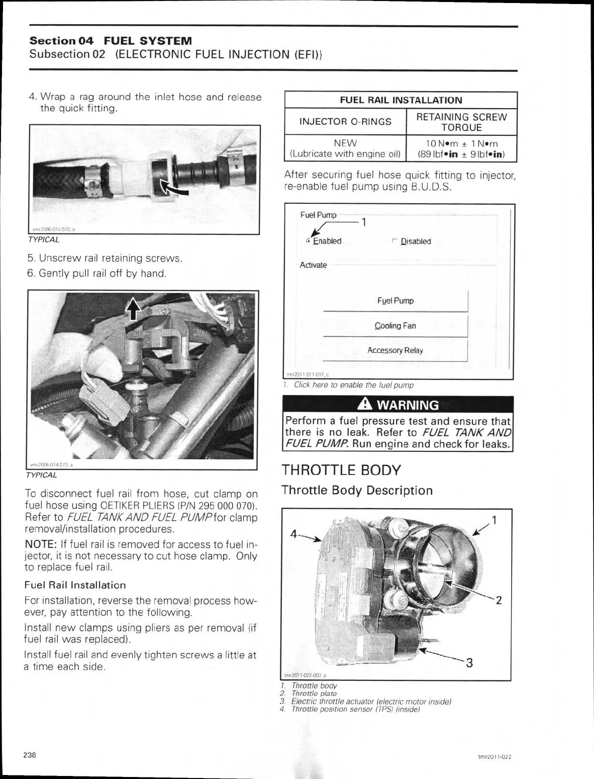
THROTTLE BODY
Throttle Body Description
1.
Throttle body
2.
Throttle plate
3.
Electric throttle actuator (electric motor inside)
4.
Throttle position sensor (TPS) (inside)
238
tmr2011-022