Section 07 CHASSIS
Subsection 05 (BRAKES)
GENERAL
During assembly/installation, use the torque val-
ues and service products as in the exploded
view(s).
Clean threads before applying a threadlocker. Re-
fer to
SELF-LOCKING FASTENERS
and LOCTITE
APPL/CAT/ONat
the beginning of this manual for
complete procedure.
A
WARNING
Torque wrench tightening specifications
must strictly be adhered to.
Locking devices must be replaced when re-
moved (e.g.: locking tabs, cotter pins, etc.).
A
WARNING
Always check brake system operation after
removing or servicing a brake component. If
brake pedal feels spongy, make sure all com-
ponents are properly installed and system is
properly bled.
NOTICE
Avoid spilling brake fluid on plastic,
rubber or painted parts. Protect these parts
with a rag when servicing brake system.
NOTICE
Sealing washers must be discarded
and replaced with new ones every time a Banjo
fitting is unscrewed.
NOTICE
Hoses, cables and locking ties re-
moved during a procedure must be reinstalled
as per factory standards.
NOTE: Always clean the area around a brake com-
ponent before servicing.
INSPECTION
BRAKE SYSTEM PRESSURE
VALIDATION
NOTICE
Do not pump up the brake pedal re-
peatedly before doing the validation.
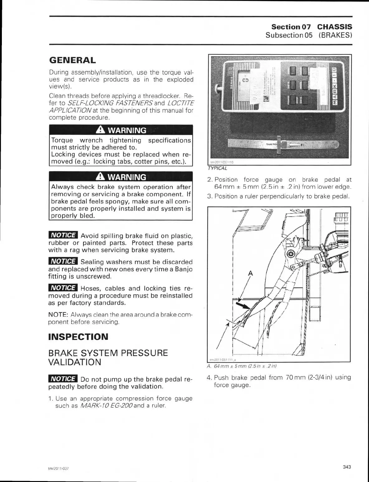
1. Use an appropriate compression force gauge
such as
MARK-10 EG-200
and a ruler.
TYPICAL
2.
Position force gauge on brake pedal at
64 mm ± 5 mm (2.5 in ± .2 in) from lower edge.
3.
Position a ruler perpendicularly to brake pedal.
A. 64 mm ± 5 mm (2.5 in ± .2 in)
4.
Push brake pedal from 70 mm (2-3/4 in) using
force gauge.
trnr2011-037
343
 Loading...