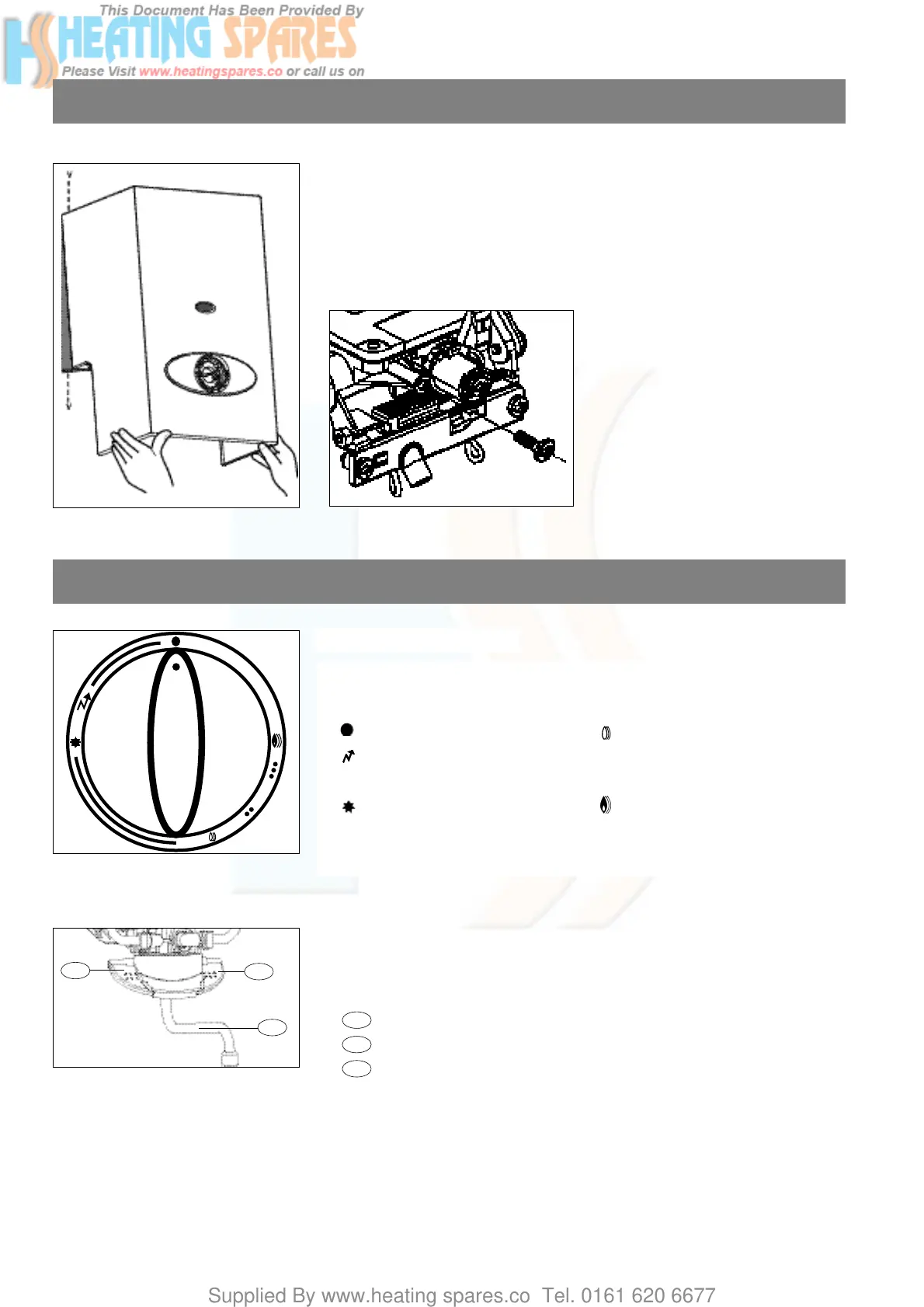
5. Fitting the case
- remove the protective film from the case
- fit the two pinch nuts, delivered in the accessories pouch, on the deflector
- position the case top-first (fig. 10)
- fit the four screws “v”
- fit the fascia attachment screw (fig. 10a) (supplied in the accessories pouch)
- fit the gas control knob.
6
Fig. 10
6. Controls and use
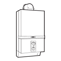
Fig. 11
Control panel (fig. 11):
Gas control knob symbols :
: Off : Reduced power
: Pilot ignition
•
•
:
Intermediate
piezo triggering
•
•
•
:
powers
: Pilot position
: Maximum power
Note : The shape and colour of the control panel may differ according to the model.
Controls
Fig. 10a
Fig. 12
Built-in mixer tap (fig. 12) :
The "A.M.I." models incorporate a mixer tap with "quick-connect" ceramic heads for
use over a draw-off point.
This mixer tap comprises :
: a cold water lever
: a hot water lever
: spout
26
25
24
25
24
26