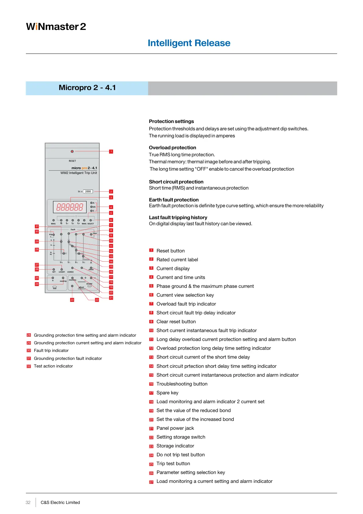
Protection settings
Protection thresholds and delays are set using the adjustment dip switches.
The running load is displayed in amperes
Overload protection
True RMS long time protection.
Thermal memory: thermal image before and after tripping.
The long time setting "OFF" enable to cancel the overload protection
Short circuit protection
Short time (RMS) and instantaneous protection
Earth fault protection
Earth fault protection is definite type curve setting, which ensure the more reliability
Last fault tripping history
On digital display last fault history can be viewed.
Reset button
Rated current label
Current display
Current and time units
Phase ground & the maximum phase current
Current view selection key
Overload fault trip indicator
Short circuit fault trip delay indicator
Clear reset button
Short current instantaneous fault trip indicator
Long delay overload current protection setting and alarm button
Overload protection long delay time setting indicator
Short circuit current of the short time delay
Short circuit prtection short delay time setting indicator
Short circuit current instantaneous protection and alarm indicator
Troubleshooting button
Spare key
Load monitoring and alarm indicator 2 current set
Set the value of the reduced bond
Set the value of the increased bond
Panel power jack
Setting storage switch
Storage indicator
Do not trip test button
Trip test button
Parameter setting selection key
Load monitoring a current setting and alarm indicator
1
2
3
4
5
6
7
8
9
10
11
12
13
14
17
19
20
21
22
18
16
15
23
24
25
26
27
1
5
6
7
8
9
10
11
12
13
21
20
19
18
17
16
15
14
31
30
29
28
24
Grounding protection time setting and alarm indicator
Grounding protection current setting and alarm indicator
Fault trip indicator
Grounding protection fault indicator
Test action indicator
28
29
30
31
32
22
23
Micropro 2 - 4.1
32 C&S Electric Limited
33
C&S Electric Limited
Intelligent Release Intelligent Release
RESET
micro 2 - 4.1pro
WM2 Intelligent Trip Unit
2000In =
G L1 L2 L3
MAX.MAX. SELECT
A
kA
S
2
3
4
SET
26
LOAD1
27
LOAD2
lr4 lr1 lr2 lr3
A
check
Fault
clear
trip
S
t
l
tS
tG
nontrip
test
memory
adjust
DC24V
ti
25
Time setting
Time delay (s)
lr= In x
Tripping between 1.05 and 1.2 x lr
Current Setting (A)
Over Load Protection
Micropro 2 - 4.1
0.4 ........................... 1, OFF
tr (s)
15 30 60 120 240
OFF
1.5xlr
15 30 60 120 240
480
2xlr
8.4 16.9 33.8 67.5 135
270
7.2xlr
0.65 1.3 2.6 5.2 10.4
20.8
Thermal memory
300 min
Output DO single alarm
Time setting
Time delay (ms) Accuracy ± 40ms
Short time lsd
2
l t on I > 8Ir
100 200 300 400
lsd = lr x
Pick-up (A)
0.4 ..........................15, OFF
2
l t on I < 8Ir
tsd (s)
0.1 0.2 0.3 0.4
t=
2
(8lr)
tsd
2
l
Time setting
Instantaneous li
li = lnx
Pick-up (A)
1..........................50kA, OFF
Instantaneous
Time setting
Time delay (ms) Accuracy ± 40ms
Earth fault lg
tg (s)
0.1 0.2 0.3 0.4
lg =In x
Pick-up (A)
0.2 .............................1, OFF
tg (s)
0.1 0.2 0.4 OFF
Min. (ms)
Max. (ms)
60 160 255 340
140 240 345 460
Indication, Monitoring & Control
Power On Led indicator
Overload LED indicator
Overload trip LED indicator
Short circuit trip LED indicator
Earth fault trip LED indicator
Trip history
Thresholds and delay setting by dip switches
Test function
Load monitoring
(Earlier terminology Long time lr1, Short Time lr2, Instantaneous lr3, Earth fault lr4)
W Nmaster 2iW Nmaster 2i
Available
 Loading...