8
L
evel the appliance using the feet as
illus
trated in figure 8:
a.
tu
rn the nut clockwise to release the
scr
e
w;
b. rotate the foot to raise or lower it until it
touches to the floor;
c.
lock the foot, screwing in the nut, until it
ti
ghtens against
was
hing machine.
P
l
ug in the appliance.
The deter
gent draw is split into 3
com
partments as illustrated in figure 9:
compar
tment "1": for prewash detergent;
compar
tment “
”
sof
teners, starch fragrances, etc.;
compar
tment "2": for washing detergent.
A
liquid detergent cup is also included
SOM
E MODELS (fig. 10)
in com
partment "2"
. T
his way, liquid
detergent will only enter the drum at the
rig
ht time. T
he cup c
an also be used for
bleach when the “Rinse” program is
sel
ected.
2
1
9
10
WARNI
NG:
contact the Customer Service Centre
should the power cord need
replacement.
De
tergent drawer
WARNI
NG:
only use liquid products; the washing
machine is set to automatically dose
additives at each cycle during the last
rinse.
WARNI
NG:
some detergents are hard to remove.
In this case we recommend using the
specific container to be placed in the
drum (example in figure 11).
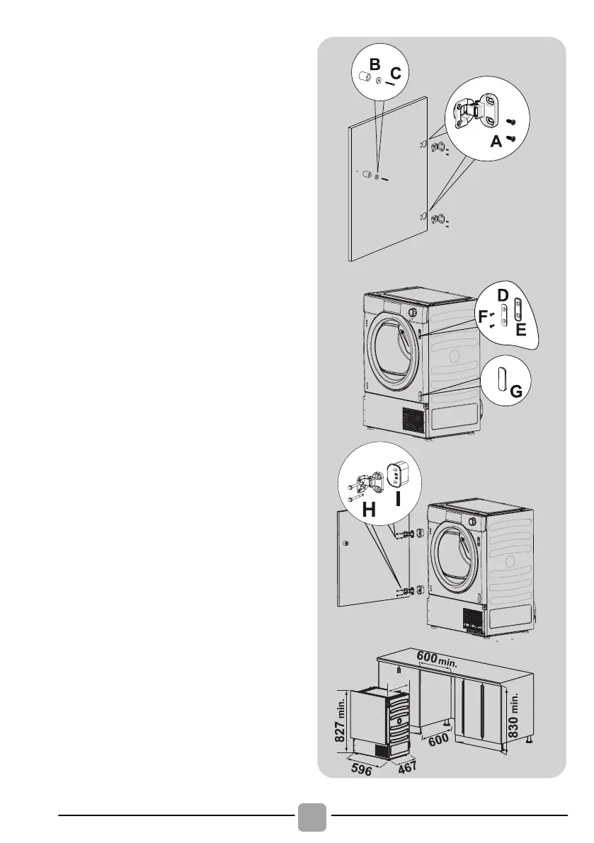
Fix the
hinges in place (on the
door)
provided (A) (figure 4).
Fix the m
agn
using screw (C) (figure 4).
Mount the plate (D) on the right
or left-
your installation requirements
(figure
5).
Place the plastic support (E)
under the
plate and fix it in
position wit
h screw (F) (figure 5)
.
Snap moun
lower position (figure 5).
Mount the furniture door to the
front of the dryer using the
hinges. Place
the spacers
under the hinges (I)
(figure 6)
and then fix in
screw (H).
Slide the dryer into an opening
of the size indicated in the
diagram (figure 7).
Figure 4:
Figure 5:
Figure 6:
Figure 7:
Fix the hinges in place (on the
door)
provided (A) (figure 4).
Fix the m
agn
using screw (C) (figure 4).
Mount the plate (D) on the right
or left-
your installation requirements
(figure 5).
Place the plastic support (E)
under the plate and fix it in
position wit
h screw (F) (figure 5)
.
Snap moun
lower position (figure 5).
Mount the furniture door to the
front of the dryer using the
hinges. Place the spacers
under the hinges (I)
(figure 6)
and then fix in
screw (H).
Slide the dryer into an opening
of the size indicated in the
diagram (figure 7).
Figure 4:
Figure 5:
Figure 6:
Figure 7:
'R
QRWLQVWDOOWKHSURGXFWLQD
ORZ WHPSHUDWXUH URRP RU LQ D
URRPZKHUHWKHUHLVDULVNRIIURVW
RFFXUULQJ$WWHPSHUDWXUHDURXQG
IUHH]LQJ SRLQW WKH SURGXFW PD\
QRW EH DEOH WR RSHUDWH SURSHUO\
WKHUH LV D ULVN RI GDPDJH LI WKH
ZDWHULVDOORZHGWRIUHH]HLQ WKH
K\GUDXOLF FLUFXLW YDOYHV KRVHV
SXPSV )RU D EHWWHU SURGXFW
SHUIRUPDQFH WKH DPELHQW URRP
WHPSHUDWXUH PXVW EH EHWZHHQ
& 3OHDVH QRWH WKDW
RSHUDWLQJ LQ FROG FRQGLWLRQ
EHWZHHQ DQG & PLJKW
VLPSO\VRPHZDWHUFRQGHQVDWLRQ
DQGZDWHUGURSVRQIORRU
3UHYHQW LWHPV
IURP IDOOLQJ RU
FROOHFWLQJ EHKLQG WKH GU\HU DV
WKHVHPD\REVWUXFWWKHDLULQOHW
DQG RXWOHW 1(9(5 LQVWDOO WKH
GU\HUXSDJDLQVWFXUWDLQV
Ɣ
$LU2XWOHWVLQWKH%DVH
:$51,1*
7KH DSSOLDQFH
PXVWQRWEHVXSSOLHGWKURXJK
DQ H[WHUQDO VZLWFLQJ GHYLFH
VXFKDVDWLPHURUFRQQHFWHG
WR D FLUFXLW WKDW LV UHJXODU\
VZLWFKHGRQDQGRIIE\DXWLOLW\
,I
WKHVXSSO\FRUGLVGDPDJHG
LW PXVW EH UHSODFHG E\ WKH
PDQXIDFWXUHULWVVHUYLFHDJHQWRU
VLPLODUO\ TXDOLILHG SHUVRQV LQ
RUGHUWRDYRLGDKD]DUG
7KH
SOXJVKRXOGEHDFFHVVLEOHIRU
GLVFRQQHFWLRQ DIWHU WKH DSSOLDQFH
KDVEHHQLQVWDOOHG
Ɣ
487
 Loading...