Do you have a question about the Canon 2/4 Hole Puncher Unit-A1 and is the answer not in the manual?
Details the punching process, driven by the punch motor and controlled by sensors.
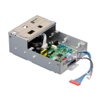
Describes the puncher controller PCB, its ICs, and their roles in unit operation.
Explains how the puncher unit detects jams using sensors and the types of jams.
Provides step-by-step instructions for removing the punch motor (M301) and punch shift motor (M302).
Details handling procedures before and after replacing the puncher controller PCB.
Outlines adjustment, operation, inspection, and setting items available in the service mode.
Provides a procedure to adjust the punch hole position when it is skewed.
Details how to adjust the horizontal registration position of the punch hole.
Explains how to adjust the punch hole position in the feed direction.
Covers procedures for handling the puncher controller PCB during replacement, including backup.
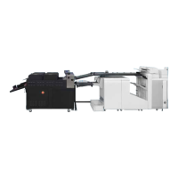
Details the step-by-step process for installing the punch unit into the finisher.
Covers checking and adjusting punch hole position, skew, and paper stop position.
| Brand | Canon |
|---|---|
| Model | 2/4 Hole Puncher Unit-A1 |
| Category | Printer Accessories |
| Language | English |