Do you have a question about the Canon i-SENSYS MF4320d and is the answer not in the manual?
| Print Technology | Laser |
|---|---|
| Functions | Print, Copy, Scan |
| Duplex Printing | Yes |
| Scanner Type | Flatbed |
| Scan Resolution | Up to 600 x 600 dpi |
| Copy Resolution | Up to 600 x 600 dpi |
| Paper Input Capacity | 250 sheets |
| Paper Output | 100 sheets |
| Connectivity | USB 2.0 |
| Operating System Compatibility | Windows, Mac OS |
| Print Speed | 22 ppm |
| Print Resolution | Up to 600 x 600 dpi |
Provides an overview of the machine's capabilities and technical details.
Identifies and labels all key external and internal components of the machine.
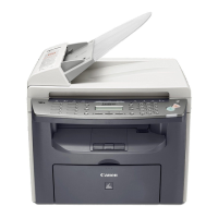
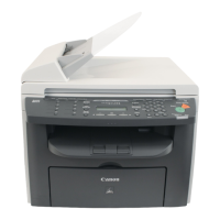
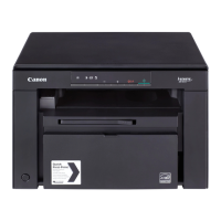
Shows a visual representation of the machine's external appearance.
Illustrates the internal layout and components of the main machine body.
Depicts the internal structure of the Automatic Document Feeder (ADF) and Duplex Automatic Document Feeder (DADF).
Details the layout and function of the machine's control panel buttons and display.
Outlines essential safety guidelines, including precautions for laser mechanisms, toner, and electrical components.
Details technical specifications for the host machine, ADF/DADF, and FAX functions.
Lists various functions including scanning ranges, recording ranges, and printer driver environments.
Describes the functional configuration and main blocks of the machine's operation.
Explains the functional blocks composing the host machine's system.
Details the operational sequence of the machine from power-on to motor stop.
Outlines the sequence of operations for the reader and engine from power supply turn-on.
Explains the fundamental construction, specifications, and major components of the original exposure system.
Lists specifications, controls, and functions related to the document exposure system.
Identifies the main components that constitute the Document Exposure System.
Provides step-by-step instructions for replacing key components like the scanner unit and reader motor.
Details the procedure for preparing and removing the scanner unit.
Provides steps for preparing and removing the flat bed motor (reader motor).
Outlines the procedure for removing the contact sensor.
Details the basic operational procedures for the ADF and DADF systems.
Explains the stream-reading operation of the Auto Document Feeder (ADF).
Describes the pickup, feed, and delivery operations for the Duplex Automatic Document Feeder (DADF).
Details the two types of original detection methods used in the equipment.
Explains how jams are detected and the procedures for releasing them.
Lists the conditions under which a paper jam is judged and the operation after detection.
Covers the removal procedures for ADF/DADF related parts like pickup rollers, motors, and separation pads.
Provides instructions for removing the ADF and DADF pickup rollers.
Details the preparation and removal procedures for the ADF motor.
Outlines the procedures for removing the ADF and DADF separation pads.
Provides an overview of the laser scanner assembly and its configuration.
Explains the composition and operation of the laser scanner assembly.
Details how the laser activation timing is controlled, including ON/OFF operations.
Describes the control mechanism for turning the laser diode ON or OFF.
Explains the Auto Photoelectric Current Control (APC) for managing laser light intensity.
Details the procedure for controlling laser current to maintain a specific target laser level.
Describes the control mechanisms for the laser scanner motor, including speed and fault detection.
Provides an overview of the control circuit for the scanner motor.
Explains the process of controlling the scanner motor to rotate at a constant speed.
Details how faults in the scanner motor are detected and reported.
Provides procedures for replacing the laser scanner unit.
Details the preparation and removal steps for the laser scanner unit.
Explains the configuration and print process of the image formation system.
Describes the main parts composing the image forming system.
Details the basic operation process for image formation by the printer.
Details the generation and control of transfer charging bias for image transfer.
Explains the generation and application of transfer charging bias.
Covers the detection mechanism for the toner level in the cartridge.
Describes how the toner sensor detects the remaining toner level.
Provides instructions for removing the transfer charging roller.
Details the procedure for removing the transfer charging roller.
Describes the pickup and feeding system, including its components and operation.
Explains the pickup/feeding system and its components like motors, solenoids, and sensors.
Explains other control mechanisms related to paper pickup and feeding operations.
Details the pickup/feed operation of the machine.
Details various types of paper jams, their detection methods, and causes.
Explains the paper sensors used for jam detection and the process of judging a jam.
Describes pickup and delivery delay jams and their detection criteria.
Details pickup and delivery stationary jams and their detection criteria.
Covers other types of jams such as door open, wrapping, and residual jams.
Explains the overview and operation of the duplexing unit for double-sided printing.
Describes the duplexing pick up operation performed by the main motor.
Provides procedures for replacing parts like the main motor, separation pad, and pickup roller.
Details the preparation and removal procedures for the main motor.
Outlines the preparation and removal procedures for the separation pad.
Provides instructions for removing the pickup roller.
Describes the configuration and specifications of the fixing unit.
Lists specifications, controls, and functions related to the fixing unit.
Explains the components and operation of the fixing unit.
Details control mechanisms for the fixing unit, including temperature control and fixing modes.
Explains how the temperature of the fixing heater is controlled.
Explains the protection functions implemented to prevent fixing heater runaway.
Details the three protection functions: CPU, safety circuit, and temperature fuse.
Provides procedures for replacing the fixing unit and fixing film unit.
Details the preparation and removal steps for the fixing assembly.
Outlines the preparation and removal procedures for the fixing film unit.
Outlines the structure and control of the machine's operation panel.
Describes the components of the machine's control panel and its control system.
Details the power supply route and protection functions within the machine.
Explains the power supply route of the machine.
Describes the protecting function for overcurrent/overvoltage in the power supply PCB.
Provides procedures for removing external covers and internal PCBs.
Details the steps for removing the front cover.
Outlines the preparation and removal procedures for the rear cover.
Provides instructions for removing the right cover.
Details the procedure for removing the left cover.
Outlines the preparation and removal procedures for the upper cover.
Provides instructions for removing the printer cover (cartridge cover).
Details the procedure for removing the control panel unit.
Outlines the procedure for removing the SCNT PCB, including data output.
Details the preparation and removal procedures for the DCNT PCB.
Outlines the preparation and removal procedures for the power supply PCB.
Details the preparation and removal procedures for the high voltage PCB.
States that there are no periodically replaced parts for this machine.
Confirms the absence of periodically replaced parts.
States that there are no specific periodical service items for this machine.
Confirms the absence of specific periodical service items.
Details cleaning items, timing, and methods for various parts of the machine.
Lists the items requiring cleaning and the timing for each.
Provides instructions for cleaning the external covers of the machine.
Details the cleaning methods for various parts of the reader unit.
Explains the procedure for cleaning the pressure roller.
Covers essential adjustments for paper margins, reading alignment, and print positioning.
Details how to adjust paper margins for various functions and paper types.
Explains how to adjust reading start positions for horizontal and vertical scanning.
Provides instructions for adjusting print positioning for different paper types and trays.
Lists electrical components, including solenoids, motors, sensors, and PCBs, with their locations.
Lists the solenoids and motors used in the machine.
Lists all sensors used in the machine and their functions.
Lists the Printed Circuit Boards (PCBs) used in the machine.
Explains the purpose of error codes and lists system, scanner, printer, and communication error codes with causes and remedies.
Describes the function of error codes in indicating machine faults.
Lists various error codes, their major causes, and recommended remedies.
Introduces the service mode, including setting service data and activating the mode.
Explains the types of service data items available in Service Mode.
Provides a flowchart for activating the Service Mode.
Displays the structure of the Service Data Menu, including country/region settings and function parameters.
Details various soft switch settings (SSSW) and their functions, including bit elaborations.
Explains the structure of Soft Switch Settings (SSSW).
Lists functions and elaborates on bits 2, 3, and 5 for SSSW-SW02.
Lists functions and elaborates on bit 8 for SSSW-SW04.
Lists functions and elaborates on bits 1 and 2 for SSSW-SW10.
Lists functions for SSSW-SW16.
Lists functions and elaborates on bits 6, 7, and 8 for SSSW-SW20.
Lists functions and elaborates on bit 4 for SSSW-SW21.
Lists functions and elaborates on bits 5, 6, 7, and 8 for SSSW-SW23.
Lists functions and elaborates on bits 7 and 8 for SSSW-SW30.
Lists functions and elaborates on bits 1 to 6 for SSSW-SW37.
Lists functions and elaborates on bit 7 and 8 for SSSW-SW39.
Lists functions and elaborates on bits 3 and 4 for SSSW-SW51.
Lists functions and elaborates on bits 6 and 7 for SSSW-SW54.
Explains how to operate test modes, including print test patterns and hardware tests.
Provides an outline of the test mode operations.
Details tests for print patterns, sensors, and keys.
Lists service tools, including solvents and lubricants, with their purpose and usage.
Provides a table of solvents and lubricants used for maintenance.