EasyManua.ls Logo

Canon L100 User Manual

Canon L100
186 pages
To Next Page IconTo Next Page
Page #1 background imageLoading...
Page #1 background image
87654321
Service Manual Rev.0
L100 / L150 / 154 / L170 / L174 Series

Table of Contents

Question and Answer IconNeed help?

Do you have a question about the Canon L100 and is the answer not in the manual?

Canon L100 Specifications

General IconGeneral
Print TechnologyLaser
Print Resolution600 x 600 dpi
Paper Capacity150 sheets
ConnectivityUSB 2.0
TypeLaser Printer
Operating System CompatibilityWindows, Mac OS

Summary

Safety Precautions

Laser Safety

Safety information regarding laser beams.

Product Overview

Technical Overview

Periodical Services

Disassembly/Assembly

External Cover

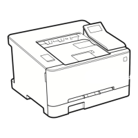
Procedures for removing external covers.

Controller System

Disassembly of the controller system.

Original Exposure System

Disassembly of the original exposure system.

Laser Exposure System

Disassembly of the laser exposure system.

Image Formation System

Disassembly of the image formation system.

Fixing System

Disassembly of the fixing system.

Pickup Feed System

Disassembly of the pickup feed system.

Laser Safety

ADF Specifications

Operation Panel (L100 / L170 / L174)

Operation Panel (L150 / L150 CHN / L150 KOR / L154)

Print Sequence

Power-On Sequence

Controller System

Main Controller

Role and function of the main controller.

Engine Controller

Role and function of the engine controller.

Power Supply

Service Tasks

At parts replacement

Tasks required when replacing parts.

Original Exposure System

Detecting Jams

Laser Exposure System

Image Formation System

Print Process

Steps involved in the printing process.

Static Latent Image Formation Block

Development Block

Transfer Block

Fixing Block

Drum Cleaning Block

High-Voltage Control

Fixing System

Fixing Temperature Control

Heater Temperature Control

Control of the fixing heater temperature.

Protective Functions

Functions to prevent overheating.

Throughput Down Control

Throughput Down Sequence

Sequence for reducing throughput.

Pickup Feed System

Detecting Jams

Methods for detecting paper jams.

Delay Jam

Delivery Delay Jam

Detection of delays in paper delivery.

Stationary Jam

Pickup Stationary Jam

Stationary jams during pickup.

Delivery Stationary Jam

Stationary jams during delivery.

Electrical Components

ADF Unit (L100/L170/L174/L250/L150 CHN/L150 KOR/L154)

Electrical components of the ADF Unit.

ADF Unit (L150 EUR/L150 AUS)

Heater/Thermistor/Thermoswitch/

PCB

External Cover

Removing the ADF Left Cover

Removing the ADF Right Cover

Removing the Handset Base Unit (L100/L170/L174/L250/L150 CHN/L150 KOR/L154)

Removing the ADF Left Upper Cover (L150 EUR/L150 AUS)

Removing the Left Cover

Removing the Right Cover

Removing the Front Cover Unit

Removing the Rear Cover

Removing the Upper Cover

Removing the Operation Panel Unit

Removing the Drive Belt

Removing the Main Motor

Removing the Main Controller PCB

Before Replacing the Main Controller PCB

Steps before replacing the PCB.

Removing the Engine Controller PCB

Removing the Communication PCB Unit

Removing the NCU PCB

Removing the Paper Leading Edge Sensor

Removing the Fixing Delivery/Paper Width Sensor PCB

Removing the Toner Sensor

Removing the Speaker

Removing the ADF Unit

Removing the ADF Upper Unit (L100/L170/L174/L250/L150 CHN/L150 KOR/L154)

Removing the ADF Upper Unit (L150 EUR/L150 AUS)

Removing the Document Feed Tray

Removing the ADF Upper Unit and ADF Lower Unit (L100/L170/L174/L250/L150 CHN/L150 KOR/L154)

Removing the ADF Upper Unit and ADF Lower Unit (L150 EUR/L150 AUS)

Removing the CIS Unit

Removing the ADF Pickup Roller

Removing the ADF Feed Roller

Removing the ADF Separation Pad

Removing the ADF Delivery Roller

Removing the Laser Scanner Unit

Removing the Transfer Roller

Removing the Fixing Assembly

Removing the Pickup Unit

Removing the Pickup Roller

Removing the Pickup Solenoid

Removing the Separation Pad

Adjustment

Electrical Adjustment

Adjustments related to electrical components.

Electrical Adjustment

Electric part-related adjustment

Adjustments for electrical parts.

Trouble Shooting

Test Print

Using test prints for troubleshooting.

Trouble Shooting Items

Common troubleshooting issues.

Version Upgrade

Procedures for upgrading firmware.

Log Collector

Tool for collecting operational logs.

Test Print

Test Print Function

How to use the test print function.

Trouble Shooting Items

Image Faults

Troubleshooting image quality problems.

Mechanical Adjustment

Confirming Nip Width

Procedure to check the nip width.

Version Upgrade

Downloading System Software

Log Collector

Operation Procedure

Steps for operating the log collector.

Error Codes

Error Codes

List and descriptions of error codes.

Overview

Service Mode Menu

Structure and navigation of the service mode menu.

Error Codes

FAX Error Code

Service Mode

COPIER

Service mode functions related to the copier.

TESTMODE

Service mode functions for testing.

COPIER

FUNCTION

CLEAR

Clearing various data.

FEEDER

ADJUST

Feeder adjustments.

FAX

List of SSSW

List of SSSW settings for fax.

List of MENU

TESTMODE

General Circuit Diagram

General Timing Chart

Related product manuals