PC-D320/PC-D340/FAX-L400 Chapter 3: Assembly and Disassembly
3-12
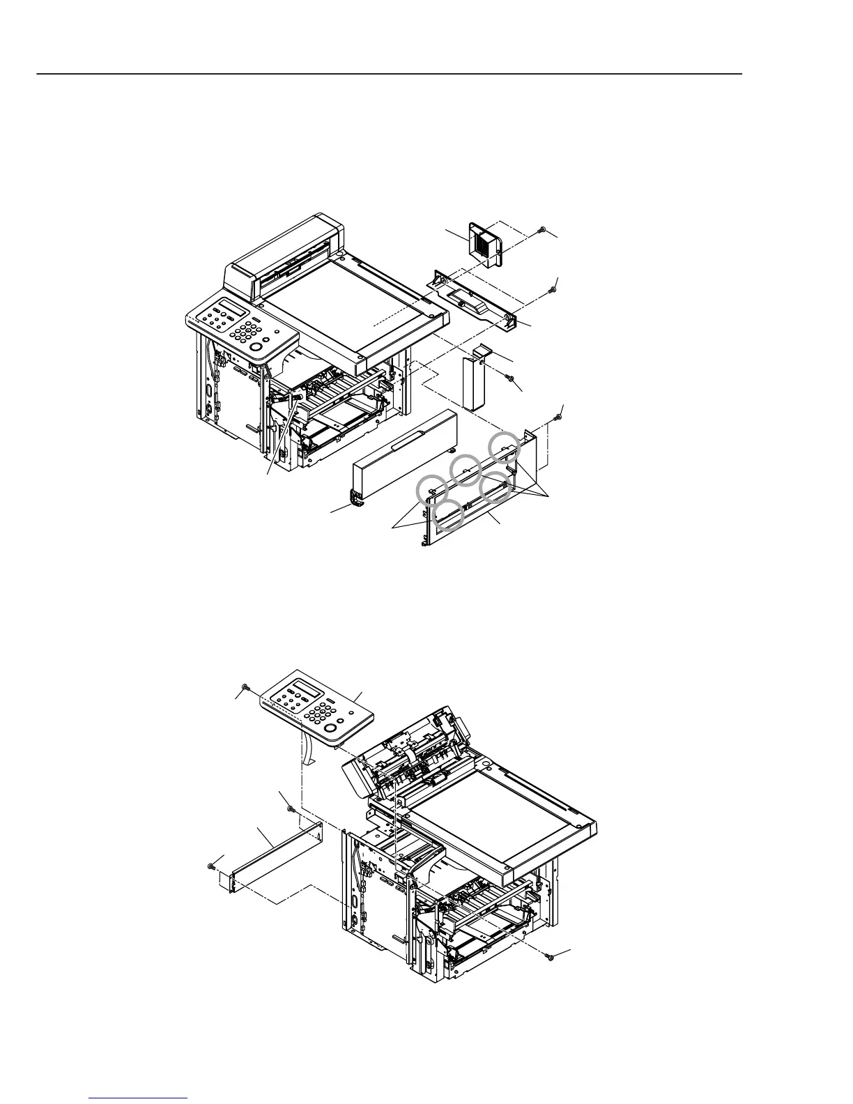
(4) Remove the 2 screws (c), and detach the right cover while removing the 5 claws.
(5) Remove the 2 interlocks of the cartridge cover arm, and detach the cartridge cover.
(6) Remove the 5 screws (d), and detach the fan cover, the rear bottom cover, and the rear
right cover.
Figure 3-13 Recording Section 3
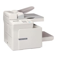
(7) Disconnect the connector J503 on the SCNT board, and detach the 2 screws (e);
remove the operation panel ass’y.
(8) Remove the 4 screws (f), and detach the left stay.
Figure 3-14 Recording Section 4
Fan cover
Rear bottom
cover
Rear right cover
Cartridge cover
Claws
Claws
Cartridge cover arm
Right cover
c
d
d
d
Operation panel ass'y
Left stay
e
f
f
e