Do you have a question about the Canon Puncher Unit-P1 and is the answer not in the manual?
Provides detailed technical specifications for the puncher unit, including performance and physical attributes.
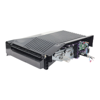
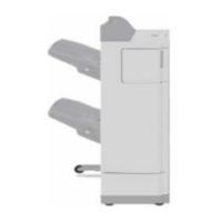
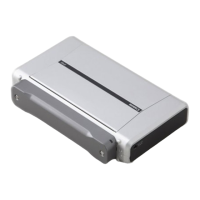
Identifies and illustrates the various external and internal parts of the puncher unit for reference.
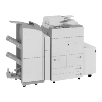
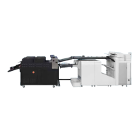
Explains the fundamental structure and placement of the puncher unit within the delivery path.
Describes the system responsible for feeding paper and driving the punching mechanism, including motors and sensors.
Details the conditions and sensors used by the finisher unit to identify and signal paper jams.
Outlines the power supply routes for the puncher unit and its protection functions.
Details the procedures for removing the external covers of the puncher unit, including rear and upper covers.
Provides step-by-step instructions for removing and replacing key drive system components like punch motors.
Details the procedures for removing and replacing electrical components such as PCBs, harnesses, and sensors.
Details user-level maintenance tasks, such as punch waste removal, performed when prompted.
Covers periodic maintenance, inspections, and replacement of parts, including sensor cleaning.
Details procedures for adjusting the punch hole position and sensor output after parts replacement.
Provides guidance on diagnosing and resolving errors using error codes, including specific fault conditions.
Lists and describes electrical components such as sensors, microswitches, motors, and PCBs used in the puncher unit.
Details specific VRs, LEDs, and check pins on the punch controller PCB relevant for field servicing.
Explains the process of upgrading the unit's firmware using a downloader PCB and service tool.
Lists recommended solvents and oils for cleaning and lubricating puncher unit components during maintenance.
Explains how the finisher unit detects faults and communicates them to the host machine as codes.
Details user-level error codes related to punch scrap full and punch scrap overflow, and how to reset them.
Lists and describes service error codes (E503, E505, E590) and their detection timing and causes.
| Brand | Canon |
|---|---|
| Model | Puncher Unit-P1 |
| Category | Printer Accessories |
| Language | English |