Version 16.02.2010
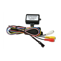
2.1. Place of installation
Carefully remove the decorational covers of the
navigation system. Loosen the 5 TORX screws as
marked in the picture on the right and extract the
device from the center console.
Disconnect the 32pin connector from the navigation system.
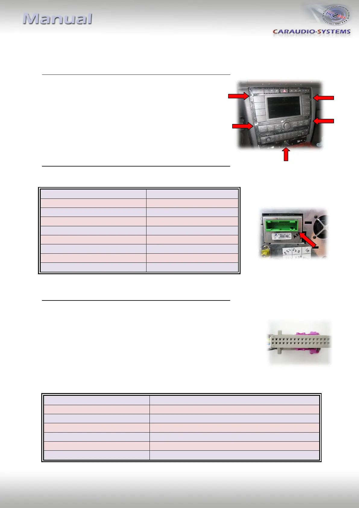
Connection assignment for the 32pin connector: Connect the pink wire
of the “Audio/Video” cable kit to Pin 23 and the green wire to Pin 24.
Connect the red wire (Audio Signal right) to Pin 10 and the black wire
(Audio Ground right) to Pin 26 (both wires are paired together).
Connect the yellow wire (Audio Signal left) to Pin 11 and the black wire
(Audio Ground left) to Pin 27 (both wires are paired together).
Connect the two black wires to Pin 8 and Pin 25.
+12V DC ( Permanent Plus )
AUDIO Signal Output (right)
AUDIO Ground Output (right)
AUDIO Signal Output (left)
AUDIO Ground Output (left)