Do you have a question about the Cardax FT Controller 3000 and is the answer not in the manual?
Overview of the Cardax FT Controller 3000 as a network-compatible device.
Details on reader connections, I/O setup, and power output for the controller.
Lists all items included in the Cardax FT Controller 3000 package.
Specifies voltage, current, and output specifications for the controller's power.
General requirements for connecting the controller, including Ethernet and EMI shielding.
Requirements for EMI cable shields on Ethernet and power cables for noise suppression.
Details on using twisted pair cable for RS485 communication between controllers.
Procedure for terminating RS232 cabling for modem communication.
Wiring guidelines for balanced inputs, including tamper detection with resistors.
Information on the eight relay outputs and their current carrying capacity.
Steps for mounting the Cardax FT Cabinet, including PCB and tamper sensor alignment.
Guidelines for installing system and power cables neatly within the cabinet.
Instructions for installing the component identification decal for wiring details.
Steps for initializing the Cardax FT Controller 3000, including setup and tamper detectors.
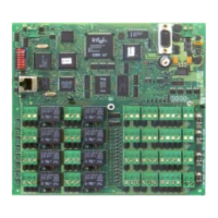
Diagram and pinout details for various connectors on the controller PCB.
Procedure for configuring the controller's MAC and IP addresses for network communication.
Steps for powering up and checking the initial sequence of the controller.
Procedure for initializing optical tamper sensors after power-up.
Table detailing the function of each dip switch and default startup configurations.
Description of the LAN Activity and Link Good LEDs for Ethernet connection status.
Table explaining the meaning of different red LED (D1) flash sequences during operation.
Step-by-step guide for safely removing the controller PCB from the cabinet.
Instructions for re-installing the controller PCB, including post-installation initialization.
Wiring diagram and pinout for the 10BaseT Ethernet connection via RJ45 socket.
Detailed voltage, current, and environmental specifications for the controller.
Specifies the maximum number of inputs, outputs, and ports supported by the controller.
Information on the resettable fuses for power in and power out connections.
Required impedance values for EMI cable shields at specified frequencies.
| voltage | 13.6 V DC ± 15% |
|---|---|
| current without relays operated | 290 mA |
| current with all relays operated | 610 mA |
| operating temperature range | -10°C to +55°C |
|---|---|
| humidity | 95% non-condensing |
| maximum number of inputs | 16 (4 state monitored) |
|---|---|
| maximum number of outputs | 8 (relay contact current rating at 24 V DC/AC 5 A resistive) |
| RS485 ports | 1 (currently not supported) |
| Ethernet ports | 1 |
| RS232 ports | 1 (plus 1 dedicated diagnostic port) |