Part number 3E1089 R3 5
March 2003
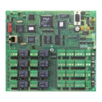
Component layout
Initialisation
Ethernet setup details
Each Cardax FT Controller 3000 has a pre-programmed, unique address (MAC address).
When the Cardax FT Controller 3000 is connected to the Ethernet, the Cardax FT Command
Centre Server (when configured) will recognise and acknowledge this address, which is
automatically linked to an IP address.
Note: The Cardax FT Command Centre Server must be configured to recognise the
Controller’s MAC address (refer to the Cardax FT Command Centre documentation).
The Server then transmits the following information to the Cardax FT Controller 3000:
- IP address for the Controller (3000 Series)
- IP address of the Server the Controller is to communicate with
The Server can then send data to, and receive data from, the Cardax FT Controller 3000.
81
OPEN
COMM
NCNO
COIL
COMM
NCNO
COIL
COMM
NCNO
COIL
COMM
NCNO
COIL
COMM
NCNO
COIL
COMM
NCNO
COIL
COMM
NCNO
COIL
COMM
NCNO
COIL
96
51
P4
HAMILTON, NEW ZEALAND
GGL ASSY 2A0203
GGL PCB 2M8170-0
CDX PCB 22920 V0
(c)2002 CARDAX (INTERNATIONAL) LTD
P3
P1
COMA
P2
SW
P4
PF4
PF3
PF2
PE4
PE3
PE2
COM
COM
COM
COM
NO NO NO NO
NC NC NC NC
COM
COM
COM
COM
NO NO NO NO
NC
NC
NC
NC
PF1 PE1
P1
0V
VIN
COMB
2
3
1
2
3
1
2
3
1
2
3
1
2
3
1
2
3
1
2
3
1
2
3
1
2
1
1
2
DETECTOR
LED
RS485
POWER
IN
0V
0V
0V
0V
VOUT
VOUT VOUT VOUT
PA4
PA3
PA2
PA1
2
1
2
1
2
1
2
1
PA4
POWER
OUT
PA3
POWER
OUT
PA2
POWER
OUT
PA1
POWER
OUT
COMB
OUT2
COMA
OUT1
DATA 1 DATA 1 DATA 1 DATA 1
DATA 0 DATA 0 DATA 0 DATA 0
PB4
PB3
PB2
PB1
2
3
1
4
2
3
1
4
2
3
1
4
2
3
1
4
COMA
OUT1
COMA
OUT1
COMA
OUT1
COMB
OUT2
COMB
OUT2
COMB
OUT2
2
3
1
IN2 IN2 IN2 IN2
GND
IN1 IN1 IN1 IN1
PC4
PC3
PC2
PC1
2
3
1
2
3
1
2
3
1
GND
GND
GND
IN4 IN4 IN4 IN4
GND
IN1 IN1 IN1 IN1
PD4
PD3
PD2
PD1
2
3
1
2
3
1
2
3
1
GND
GND
GND
PC1
PC2
PC3
PC4PD4
PD3
PD2
PD1
Front illumination
through door
P3 Auxiliary
RS232 port
RX = pin 2
TX = pin 3
DTR = pin 4
GND = pin 5
DSR = pin 6
RTS = pin 7
CTS = pin 8
RI = pin 9
SW Switch
Used during Initialisation
Refer Installation Note
Run LED
10BaseT
Diagnostic LEDs
P2 - 10BaseT
Ethernet port
Ethernet connection
P1 Power In
pin 1 = 13.6 V ± 15%
pin 2 = 0 V
PD1 to PD4
Inputs
pin 1 = Input 3
pin 2 = Ground
pin 3 = Input 4
PA1 to PA4
Power Out
pin 1 = power out
pin 2 = 0 V
P4 RS485 Bus
Front tamper
Rear tamper
Group 4
Group 3
Group 2
Group 1
Group 4
Group 3
Group 2
Group 1
Relays 1 to 8
pin 1 = Normally closed
pin 2 = Normally open
pin 3 = Common
PE1 = Relay 1
PF1 = Relay 2
PE2 = Relay 3
PF2 = Relay 4
PE3 = Relay 5
PF3 = Relay 6
PE4 = Relay 7
PF4 = Relay 8
PC1 to PC4
Inputs
pin 1 = Input 1
pin 2 = Ground
pin 3 = Input 2
PB1 to PB4
1 x Wiegand Reader
per connector
pin 1 = IN1 (Data 0)
pin 2 = IN2 (Data 1)
pin 3 = OUT1 (Beeper)
pin 4 = OUT2 (LED)
2 x Cardax IV Readers
per connector
Reader 1 = pins 1 & 3
Reader 2 = pins 2 & 4
 Loading...