21
ENG
easy/easy compact/easy split +030220791 - rel. 3.2 - 13.07.2010
In the event of defrost probe failure, the controller performs a timed
defrost with a duration equal to the value set for “dP”. The same is true if
the end defrost set point can not be reached, the defrost is stopped after
a maximum time equal to the value of dP, and the error Ed is displayed (if
enabled by A8) and stays on until a correct defrost cycle is performed.
dP: maximum defrost duration
Determines the maximum duration of the defrost (in minutes or seconds,
see parameter dC). When defrost by time is set (d0= 2/3/4) dP represents
the e ective duration of the defrost.
d4: defrost when switching the instrument on
Starts a defrost when switching the instrument on (d4= 1). This has
priority over the activation of the compressor and the continuous cycle.
Running a defrost when switching the instrument on may be useful in
special situations (e.g. frequent power failures).
Case 1: the system is subject to frequent power failures
In the event of power failures the instrument’s internal clock, which
calculates the interval between two defrosts, starting from zero, is reset. If
the frequency of the power failure were, in an extreme case, greater than
the defrost frequency (e.g. a power failure every 8 hours against a defrost
every 10 hours), the controller would never perform a defrost. In this type
of situation it is better to activate the defrost when the unit is turned on
(d4=1), above all if the defrost is controlled by temperature (probe on
the evaporator), so unnecessary defrosts are avoided or at least reduced
in duration.
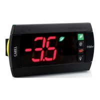
Case 2: Systems with many refrigeration units
In this situation, if the defrost on power-up is activated (d4= 1) after a
power failure all the units will start a defrost. This may cause overloads.
To avoid this, parameter “d5” can be exploited, which allows a delay to be
set before the defrost starts, a delay which obviously must be di erent
for each unit.
2
d5 (3)
dP (3)
d5 (2)
dP (2)
dP (1)
unit 1
[d4(1)= 1]
ON
OFF
ON
OFF
ON
OFF
ON
OFF
unit 2
[d4(2)= 1]
unit 3
[d4(3)= 1]
1
Fig. 4.h
Key:
1 power-up 2 voltage
d5: defrost delay on power-up or when enabled by digital input
Represents the time which must elapse between when the controller is
turned on and the start of the defrost.
The digital input can be used to start a defrost from external contact (see
parameter A4=3); d5 represents the delay between when the defrost is
enabled, or called, and when it e ectively starts. The defrost from digital
input can be exploited to perform defrosts in real time when is the RTC
option is not tted. Simply connect a timer to the multifunction digital
input. The defrost will be activated when the timer contact is closed.
In the case where more than unit is connected to the same timer, it is
recommended to set parameter d5 to delay the defrosts to a di erent
time for each unit. Furthermore, to avoid unnecessary defrosts controlled
by the instrument’s internal clock, it is suggested to set parameter dI=0
(only manual defrosts from the keypad or multifunction contact) or to set
dI to a value which is greater than the maximum set interval.
A4 Meaning d5
3 start defrost on closing delay between call and e ective
start
Table 4.f
d6: freeze control temperature display during defrost
This function locks the display of the ambient temperature during the
defrost cycle at the last value read before the current defrost (d6= 1).
d6= 0 display the message “dF” alternating with the temperature
measured by the control probe;
d6= 1 freeze the display on the last temperature measured before the
defrost.
The display normally returns when the measurement rst reaches the
set point or, in any case, after the set alarm bypass time after defrost
(parameter d8).
The freeze mode is also valid for the display of the second and third
probe, if enabled (parameter /4).
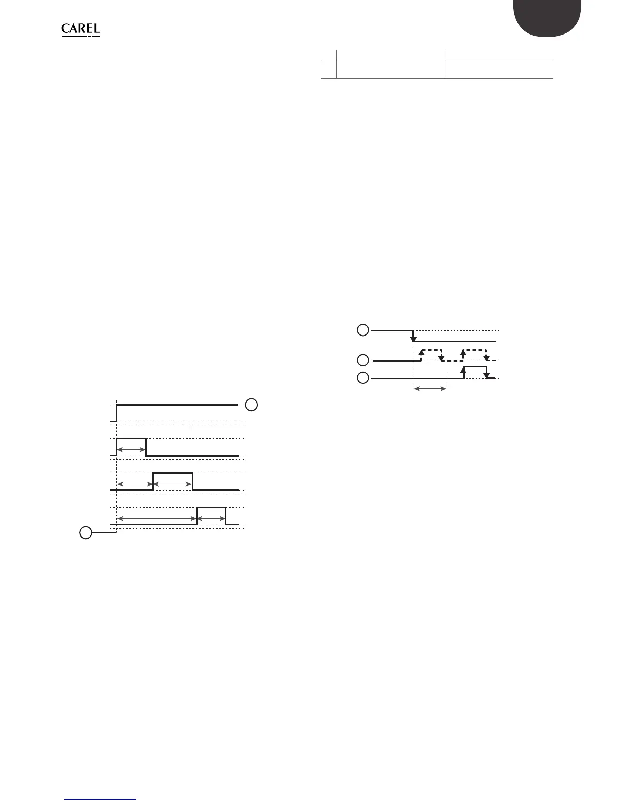
dd: dripping time
This parameter forces the compressor and the evaporator fans o after a
defrost, in order to allow the evaporator to drip.
The value of this parameter indicates the number of minutes the
compressor and fan are o . If dd = 0 no dripping is set, therefore at end
defrost the compressor starts immediately.
OFF
ON
OFF
ON
ON
OFF
dd
1
2
3
Fig. 4.i
Key:
1 defrost;
2 start compressor call;
3 compressor.
d8: alarm bypass time after defrost
The parameter has two e ects:
1. it delays the temperature alarm signal after a defrost;
2. it delays the temperature alarm signal after opening the door. In this
case, it is only active when A7=0.
d9: defrost priority over compressor protectors
Cancels the compressor protection times (c0, c1, c2, c3) at the start of the
defrost. The possible values are:
d9= 0 protection times observed;
d9= 1 protection times ignored; the defrost has higher priority and
the compressor times are not observed.
It is useful, for example, with hot gas defrost to avoid delaying the
defrost in the case where the compressor has just stopped and there is a
minimum time between two starts. Remember, however, that in this case
the maximum number of activations per hour of the compressor may
not be respected.
d/: defrost probe reading
Used to display the value measured by the defrost probe on the
instruments where this is tted.