FCP manual
Code +030220391 – rel 1.2 25/03/08
36
10. Specifications and connections
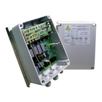
10.1 FCPM082010 / FCPM0420A0 electrical specifications
Power supply 230 Vac single-phase. -15% +10% 50/60 Hz
Analogue outputs 1 phase control 0-230 Vac single-phase:
maximum current: 8A FCPM08*
4A FCPM04*
Digital outputs 1 phase control function for expansion with auxiliary power devices, MCHRTF*
0-5 V 5 mA max;
Analogue inputs 1 configurable input for
- ratiometric pressure probes 0-5V
- std Carel NTC temp. probes (10kΩ @25°C) range of measurement: –50°C +90°C
- std Carel NTC temp. probes (50kΩ @25°C) range of measurement: 0°C +120°C
- 0/10V control (Rin: 20 kΩ)
1 configurable input for
- ratiometric pressure probes 0-5V
- std Carel NTC temp. probes (10kΩ @25°C) range of measurement: –50°C +90°C
- std Carel NTC temp. probes (50kΩ @25°C) range of measurement: 0°C +120°C
1 configurable input for
- std Carel NTC temp. probes (10kΩ @25°C) range of measurement: –50°C +90°C
- std Carel NTC temp. probes (50kΩ @25°C) range of measurement: 0°C +120°C
measurement precision (excluding the probes):
- ratiometric probes: 1%
- 0/10V control: 5% (typical 2%)
- NTC probes 10kΩ: ±1°C [-10/50]; ±2°C [-40/-10 and 50/90]
- NTC probes 50kΩ: ±1°C [30/90]; ±2°C [0/30 and 90/120]
Digital inputs 1 input with voltage free contact
typical voltage 12 V with contact open, typical current 6 mA with contact closed.
Serial outputs 1 standard RS485 two wire connector [NOTE 1]
Carel supervisor and ModBus protocol; baud rate 19200; max length 1 km with shielded cable
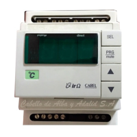
Signal lights Green power LED
Red alarm LED
Yellow serial connection active LED (flashes when receiving valid frame)
Controller settings 4 trimmers for manually setting:
- set point
- differential
- minimum speed
- maximum speed
4 dipswitches:
- select manual setting or configuration by parameters
- select function associated with the digital input
- enable double circuit (probe B2)
- enable Cut-off (or other settable function)
2 jumpers:
- 0/10V input configuration
Terminals and connectors Power supply and analogue outputs:
Screw terminals for cable cross-section min. 2.5 mm
2
max 4 mm
2
.
Signals:
Spring terminals for cable cross-section max 2.5mm
2
.
4 pin JST connector for programming key
Operating conditions -20/+50°C, <90% rH non-condensing
Storage conditions -20/+70°C, <90% rH non-condensing
Index of protection IP54
Environmental pollution 2
Protection against electric shock Class I
PTI of the insulating materials 250V
Period of stress across the insulating parts Long
Type of action -disconnection 1Y
Category of resistance to heat and fire Category D (UL94 – V0)
Immunity against voltage surges Category II
Ageing characteristics 60,000 operating hours
No. of automatic operating cycles 100,000
Software class and structure Class A
Case Metallic (Al) with plastic cover (ball pressure test 75°C)
Dimensions 140x135x90 mm
Assembly Metal case fastened to panel or wall mounted using 4 screws dia. 3.5/4 mm
Certification EMC:
EN 61326-1, EN 55014-1, EN 55014-2
Safety:
EN 60730-1
Table 10.a
Note 1:
The FCSER00000 option is required

 Loading...