Do you have a question about the Carel FCR3 and is the answer not in the manual?
Covers general safety precautions for CAREL products, including environmental and handling guidelines.
Provides information on the correct handling of waste electrical and electronic equipment according to EU directive.
Key characteristics of the FCR device and its capabilities, including power supply and input types.
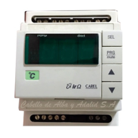
Explains controller status via LEDs and setting methods using trimmers and dipswitches.
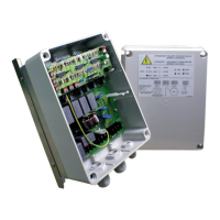
Covers installation steps, safety precautions, and environmental considerations for the controller.
Details manual and standard internal parameter settings via dipswitches and trimmers.
Explains advanced parameter programming via serial link by expert personnel.
Outlines the default parameter settings for the FCR controller.
Describes the use of programming keys for copying controller parameters.
Explains control modes based on analogue signals and input override.
Details setting the minimum and maximum output voltage levels for the controller.
Describes the controller's response to no control signal (minimum or cut-off).
Explains the linear and quadratic conversion of input signals to output voltage.
Covers controlling the output at a set value via serial connection.
Details alarm activation, effects, and management via digital inputs and temperature.
Explains temperature alarm activation, thresholds, and status indication.
Provides a comprehensive table summarizing all operating parameters.
Lists alarms indicated by the red LED, their causes, and possible conditions.
Explains signals indicated by green and blue LEDs for power and serial connection status.
Details the Modbus protocol support for slave mode and supported function codes.
Lists electrical specifications, power supply, inputs, outputs, and terminals.
Illustrates the electrical connection diagrams for different models.
Provides dimensions, assembly details, and mounting information.
Shows the layout for cable connections for different FCR3 models.
| Model | FCR3 |
|---|---|
| Display | LCD |
| Number of Inputs | 6 |
| Number of Outputs | 4 |
| Input Voltage | 24 VAC/DC |
| Communication Protocols | Modbus RTU |
| Digital Inputs | 4 |
| Analog Inputs | 2 |
| Analog Outputs | 0 |
| Operating Temperature | -10…60 °C |
| Storage Temperature | -20…70 °C |
| Humidity Range | 10% to 90% RH (non-condensing) |
| Controller Type | Electronic expansion valve controller |