26
ENG
“FCR3 three-phase controller” +030222150 - rel. 1.3 - 12.01.2021
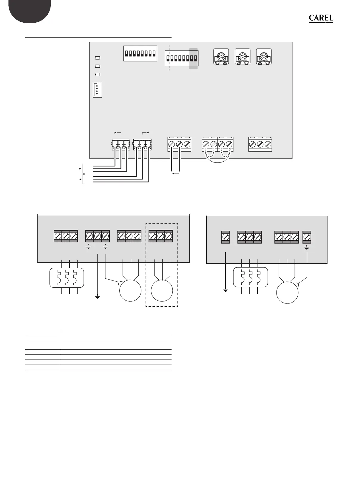
10.2 Electrical connection
1 2 3 45678
ON DIP
1
10 V
V
50 Hz
(–)
(–)
0-10 V
0-5 V
(+)
(GND)
(–)
(+)
(GND)
(+) GND
BGND SW1
DELAY
ADDRESS
Analog Input Digital Input Digital Output
MAX MIN
SW2+Vdc NC COM NO
RS485
RS485
(–) (+) GND
LIN
MIN
BAUD
PWM
I
60 Hz
QUAD
COFF
2 3 45678
ON
MAN
MEM
DIP
I
RS485
RS485
ALARM
LINK
ON
KEY
DL3
DL2
DL1
JP3
J4
J5
J1 J2 J3 J6
S1
S2
TR3 TR2 TR1
Fig. 10.g
6,9,12,20 A 40 A
L1 L2 L3 PE U V W
INPUT
OUTPUT
M 3
UVW
OUTPUT
M 3
Alimentazione trifase
Three-phase supply
L1PE L2 L3 U V W
INPUT
OUTPUT
M 3
Alimentazione trifase
Three-phase supply
Fig. 10.h Fig. 10.i
L1,L2 L3 Power supply input 400 Vac –10 to 15% 50/60 Hz
U,V,W Power supply output 400 Vac
SW1,SW2
Programmable digital input.
Motor protector or other – Terminals in series
B, GND, +VDC Analogue input
NC,COM,NO Digital output with voltage-free contact
GND, (+), (-) RS485 serial with Modbus slave supervisor protocol
KEY Programming key
 Loading...