15
ENG
“FCR3 three-phase controller” +030222150 - rel. 1.3 - 12.01.2021
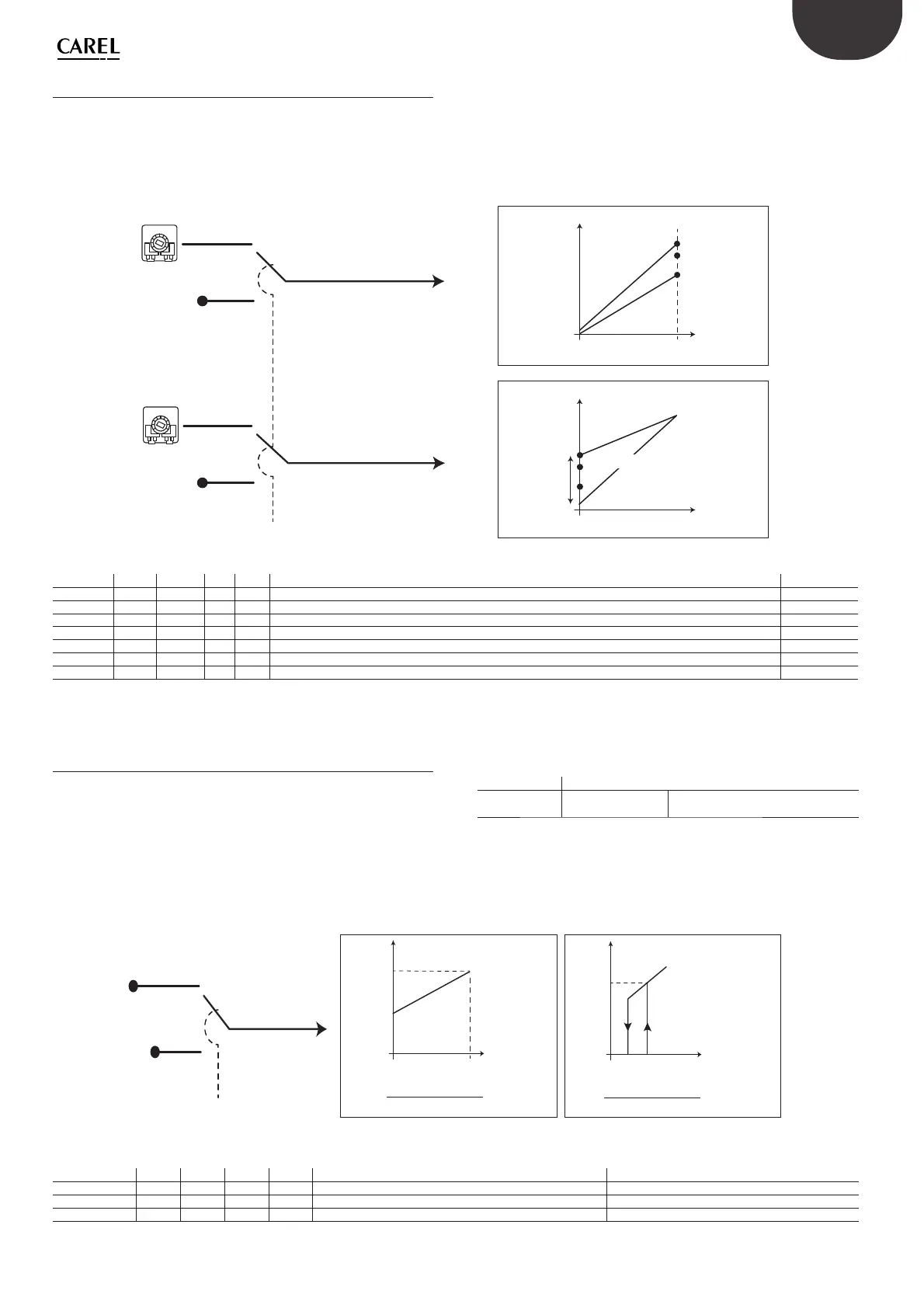
6.2 Maximum and minimum confi guration
The minimum output voltage can be set using the MIN trimmer or
internal parameter MIN FCR. Across a range of 100%, the voltage can be
set from 0 to 40% (0-160 V @ 400V).
The same applies to the maximum voltage, set using the MAX trimmer
or internal parameter MAX FCR. Across a range of 100%, the voltage can
Dipswitches Function
Dip S2.6 Minimum or Cut o
OFF: Minimum function
ON: Cut-o function
Tab. 6.d
Fig. 6.3.a illustrates the settings and the e ect on the output voltage
If selecting cut-o , the control signal must be 10% for the controller to
start again.
OUT %
IN
OUTMIN
90
MINCUT
FCR
OFF
ON
MINCUT
MEM
DIP S2.1/SEL
MINCUT
0/OFF: Minimo
1/ON: Cut.O
Out = • (IN–5)+Out min
Out max – Out min
90
OUT %
IN
OUTMAX
OUTMIN
99/1000
Out = • IN + Out min
Out max – Out min
99
Minimo Cut.O
Fig. 6.c
Associated parameters
Par. Modb Range Def UoM Description Activation
MINCUTFCR DI.4 0/1 0 1% Select minimum/cut-o from Dip S2.6 Dip S2.1=OFF
MINCUTMEM CO.4 0/1 0 1% Select minimum/cut-o from memory Dip S2.1=ON
SEL IR.1 0/1 R 1 Select parameter settings, manual =0, internal =1 (S2.1)
Tab. 6.e
be set from 50% (200V @ 400V) to 100%. The choice is always set using
dipswitch S2.1 (MAN/MEM).
Fig. 6.2.a shows how the possible e ect of the variation is processed
based on the control signal IN.
MAX
MAX
FCR
OFF
OUTMAX
50...100
0...40
OUTMIN
ON
MAX
MEM
MIN
MIN
FCR
OFF
ON
MIN
MEM
DIPS2.1/SEL
OUT
%
IN
MAX
OUTMAX
100%
99/100
50%
OUT
%
IN
MIN
40%
0%
OUTMIN
Fig. 6.b
Par. Modb Range Def UoM Description Activation
MAXFCR IR.3 50 .. 100 100 1% Manual maximum setting DIP S2.1=OFF
MINFCR IR.4 0 .. 40 40 1% Manual minimum setting DIP S2.1=OFF
MAXMEM HR.3 0 .. 40 100 1% Internal maximum setting Dip S2.1=ON
MINMEM HR.4 0 .. 40 40 1% Internal minimum setting Dip S2.1=ON
OUTMIN IR.7 0 .. 40 R 1% Minimum output value
OUTMAX IR.8 50 .. 100 R 1% Maximum output value
SEL DI.1 0/1 R 1 Select parameter settings, manual =0, internal =1 (Dip S2.1)
Tab. 6.c
6.3 Minimum and cut-off function
When there is no control signal, the controller may respond in two
di erent ways
• MINIMUM: the output voltage remains at the minimum voltage and in
practice means it never switches o .
• CUT-OFF: the controller switches o and can only switch on again
when the control signal reaches 10%. This e ectively means managing
the system with ON/OFF control
 Loading...