16
ENG
“FCR3 three-phase controller” +030222150 - rel. 1.3 - 12.01.2021
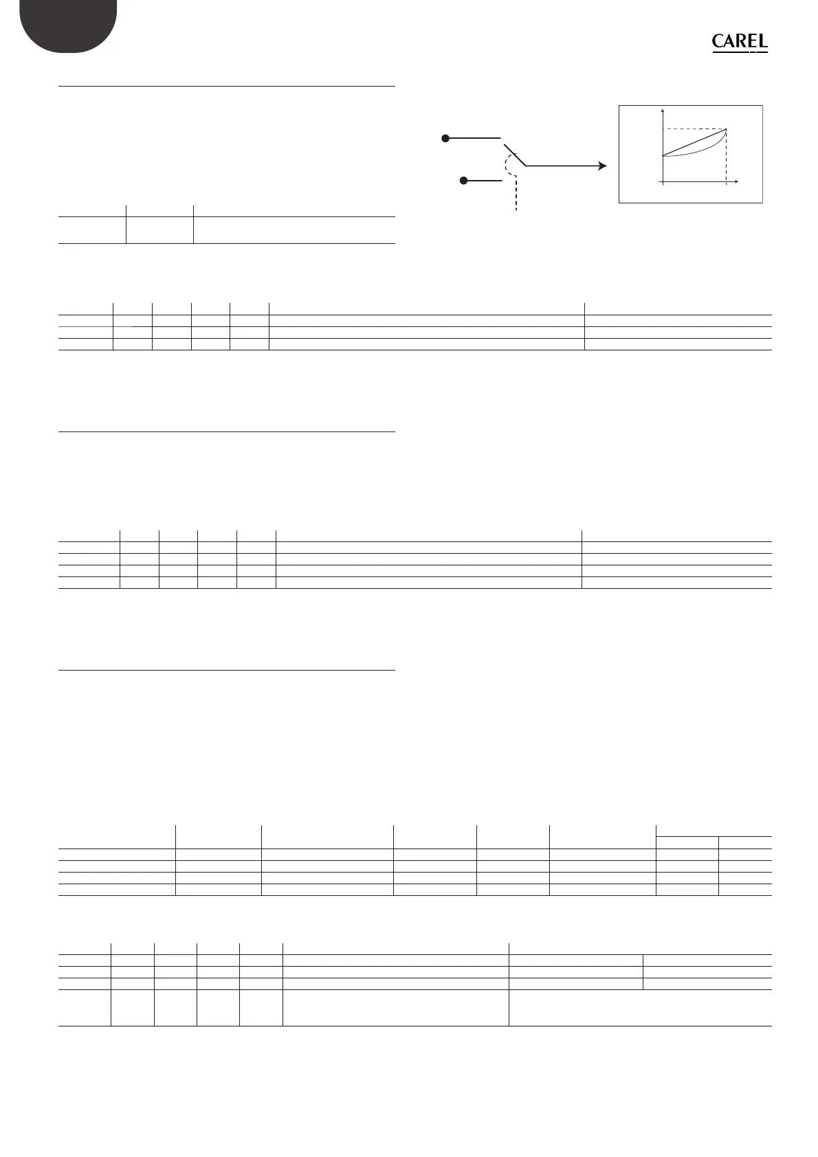
6.4 Linear and quadratic function
The output voltage can be managed so as to provide smooth variations
in the rst part of the curve or respond with a linear relationship across
the entire range, depending on the type of load.
Consequently, linear or quadratic mode can be selected
• LINEAR: the relationship between input IN and output OUT is linear
• QUADRATIC: the control signal IN is converted as IN= IN2/100, this
gives output control with a quadratic curve.
Dipswitches Function
Dip S2.5
Lineare o
Qudratica
OFF: Linear function: IN=IN
ON: Quadratic function: IN = IN
2
/100
Tab. 6.f
OFF
ON
DipS2.1/SEL
LINFCR
LINMEM
LIN
Lineare
Quadratica
0/OFF: Lineare
1/ON: Quadratica
OUT %
IN
OUTMAX
OUTMIN
99/1000
Fig. 6.d
Associated parameters
Par. Modb Range Def UoM Description Activation
LINFCR DI.3 0/1 0 1% Select linear-quadratic - dip S2.5 Dip S2.1=OFF
LINMEM CO.3 0/1 0 1% Select minimum/cut-o from memory Dip S2.1=ON
SEL IR.1 0/1 R 1 Select parameter settings, manual =0, internal =1 (S2.1)
Tab. 6.g
6.5 Override output
The output can be controlled at a set value, at any time, via the serial
connection, irrespective of the value calculated by the controller. The
function rst needs to be enabled; however detailed knowledge of the
system is required, so that sudden variations do not cause high peak
current draw. It ‘s added a delay, there are all the protections and di erent
alarms; also the output considers OUTMIN and OUTMAX limit setted.
Par. Modb Range Def UoM Description Activation
OUTFCR IR.9 0..100 0 1% Controller output value EOVR=0
OUTMEM HR.10 0..100 0 1% Output value in memory for override EOVR=1
EOVR CO.11 0/1 0 1 Override output value 0= disable, 1 = enable WE=1
WE CO.1 0/1 0 1 Enable modi cation of EOVR (WE=0 no modi cation allowed)
Tab. 6.h
6.6 Alarm conditions and management
The alarm is activated in the following cases:
• closing of the contact connected to digital input SW1 and SW2 (or
opening if set as normally closed, and closing if set as normally open)
• minimum or maximum internal temperature threshold exceeded
• built-in temperature probe short-circuited or open
Depending on the alarm, the e ects di er both regarding the controller
output, the digital output and the signal LED
The alarm from digital input has an e ect both on the parameters read,
on red LED DL3, on the relay digital output and on the controller output.
Digital input status
Dig. input
STID
Dig. input mode
MODID
Alarm ag
ALARM
LED
DL3 – Red
FCR output
Out
Relay digital output
CO-COM
SW1+SW2 = Closed 1 = Closed 0 = normally closed 0 = no alarm O normal Open Closed
SW1o SW2 = Open 0 = Open 0 = normally closed 1 = alarm On ALMO (0-50-100%) Closed Open
SW1+SW2 = Closed 1 = Closed 1 = normally open 1 = alarm On ALMO (0-50-100%) Closed Open
SW1o SW2 = Open 0 = Open 1 = normally open 0 = no alarm O normal Open Closed
Tab. 6.i
Associated parameters
Par. Modb Range Def UoM Description Stato
STIDFCR DI.10 0/1 R 1 Digital input readings 0: at least 1 open 1: both closed
MODID CO.11 0/1 0 1 Digital input logic 0: normally closed 1: normally open
ALRM DI.11 0/1 R 1 Alarm digital input status 0: inactive 1: active
ALMO HR.9 0/1/2 0 1 Output status in the event of alarms (ALRM)
0. 0%
1. 50%
2. 100%
Tab. 6.j
 Loading...