23
ENG
“FCR3 three-phase controller” +030222150 - rel. 1.3 - 12.01.2021
8. TABLES OF ALARMS AND SIGNALS
8.1 Alarms
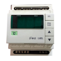
Alarms are indicated by the red LED
red LED status description
possible cause
of the alarm
o no alarm
on digital alarm input
contact open
(normally closed)
or both closed
(normally open)
blinking 1 pulse temp. probe alarm temp. probe out-of-range
Tab. 8.a
In the event of simultaneous alarms, the temperature alarm is signalled.
Only the alarm from digital input forces the output to the value de ned
by parameter ALMO and switches the digital outputs.
The alarm status is also available via serial line.
8.2 Signals
Power is indicated by the green LED. Serial connection status is indicated
by the yellow LED.
Active serial connection (link) is indicated by the blue LED
blue LED status description possible cause
o connection deactivated
cable disconnected
supervisor o ine
protocol not supported
on active connection
the connection is active,
there has been at least one valid
frame in the set time
Tab. 8.b
The serial connection is automatically deactivated after a timeout set by
variable TIMEOUT, between 15 sec and 20 minutes. By default this time
is 30 seconds