10
ENG
“FCR3 three-phase controller” +030222150 - rel. 1.3 - 12.01.2021
4. PROGRAMMING THE CONTROLLER
The controllers are programmed by dipswitches and trimmers in the MAN
mode, or by setting the internal parameters - in MEM mode, accessible
via programming key or via serial line.
4.1 Manual and standard internal
parameter programming
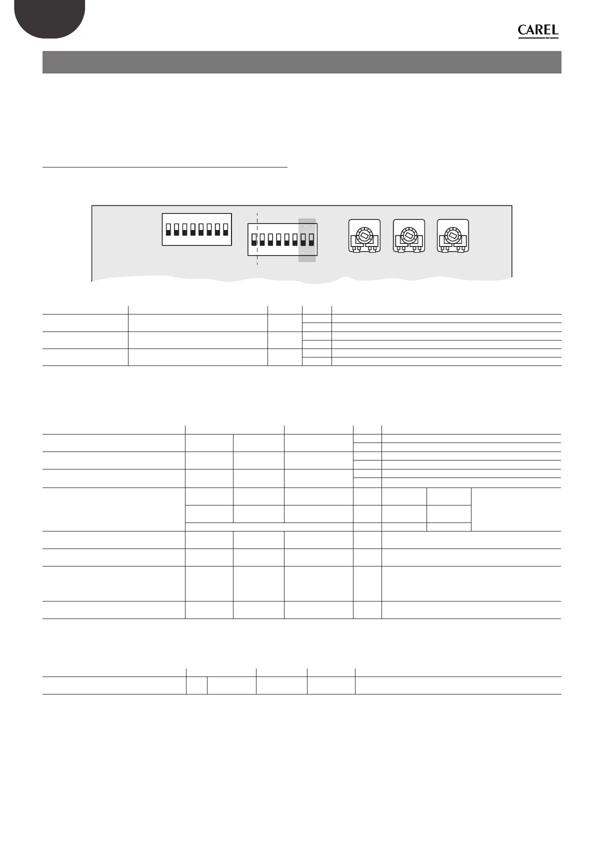
The functions that can be set manually using the dipswitches and
trimmers (Fig. 4.aa) are shown in the tables below, complete with the
Modbus variables used to read the manual settings.
12345678
ON DIP
1
10 V
V
50 Hz
DELAY
ADDRESS
MAX MIN
LIN
MIN
BAUD
PWM
I
60 Hz
QUAD
COFF
2345678
ON
MAN
MEM
DIP
Fig. 4.a
Mode dipswitches (S2) Function Modbus State Description
Dip S2.1 Select type of controller setting
SEL
DI.1
OFF: MAN: set fundamental parameters from FCR panel
ON: MEM: set parameters in internal memory
Dip S2.2 Select type of analogue inputs
OFF: 10V: 0/10 Vdc
ON: PWM: 0/5 Vdc or PWM
Dip S2.3 Select voltage/current input
OFF: V: Voltage signal (selected via Dip2)
I: Current signal (Dip2 must be ON)
Tab. 4.a
If dipswitch S2.1 is ON, the standard internal parameters are used,
equivalent to those that can be set on the panel. These have the same
name, however with the su x MEM rather than FCR.
Function FCR Manual Internal Memory State Description
Select operating frequency
Dip S2.4
HZFCR
DI.2
HZMEM
CO.2
OFF: 50 Hz
ON: 60 Hz
Select operating curve
Dip S2.5
LINFCR
DI.3
LINMEM
CO.3
OFF: LIN: linear curve
ON: QUAD: quadratic curve
Select null input mode
Dip S2.6
MICUTFCR
DI.4
MICUTMEM
CO.4
OFF: MIN: controller operates at minimum speed
ON: COFF: control o (Cut-O )
Select baud rate for serial operation
Dip S2.7
BAUD1FCR
DI.5
BAUD1FCR OFF: ON: OFF:
BAUD
Dip S2.8
BAUD2FCR
DI.6
BAUD2FCR OFF: OFF: ON:
9600 19200 38400
MINIMUM setting (MIN) TR1
MINFCR
IR.4
MINMEM
HO.4
0-40 Minimum setting from 0-40% of the input voltage
MAXIMUM setting (MAX) TR2
MAXFCR
IR.3
MAXMEM
HO.3
50-100 Maximum setting from 0-40% of the input voltage
DELAY setting (DELAY) TR3
DELAYFCR
IR.2
DELAYMEM
HO.2
0-100
Response time to an input step. The range of adjustment
from 0-100% (clockwise) corresponds to setting the time
from 0-10 sec
Input control (IN) B-GND
INFCR
IR.6
INMEM
HO.7
0-100 Control signal at analogue input
Tab. 4.b
The address parameter can be automatically selected, based on the
dipswitch settings. For details, see Table 4.a.d
Function Manual Memory State Description
Select FCR address (ADDRESS) S1
SADRFCR
IR.1
SADRMEM
HO.2
0-255 FCR
1-255 MEM
Device address
If SADRFCR=0 then the address in the memory is used
Tab. 4.c
DI = Discrete inputs R digital variables
CO= Coils R/W digital variables
IR = Input Register R integer variables
HO= Holding Register R/W integer variables
The digital variables are interpreted as 0=OFF , 1 = ON