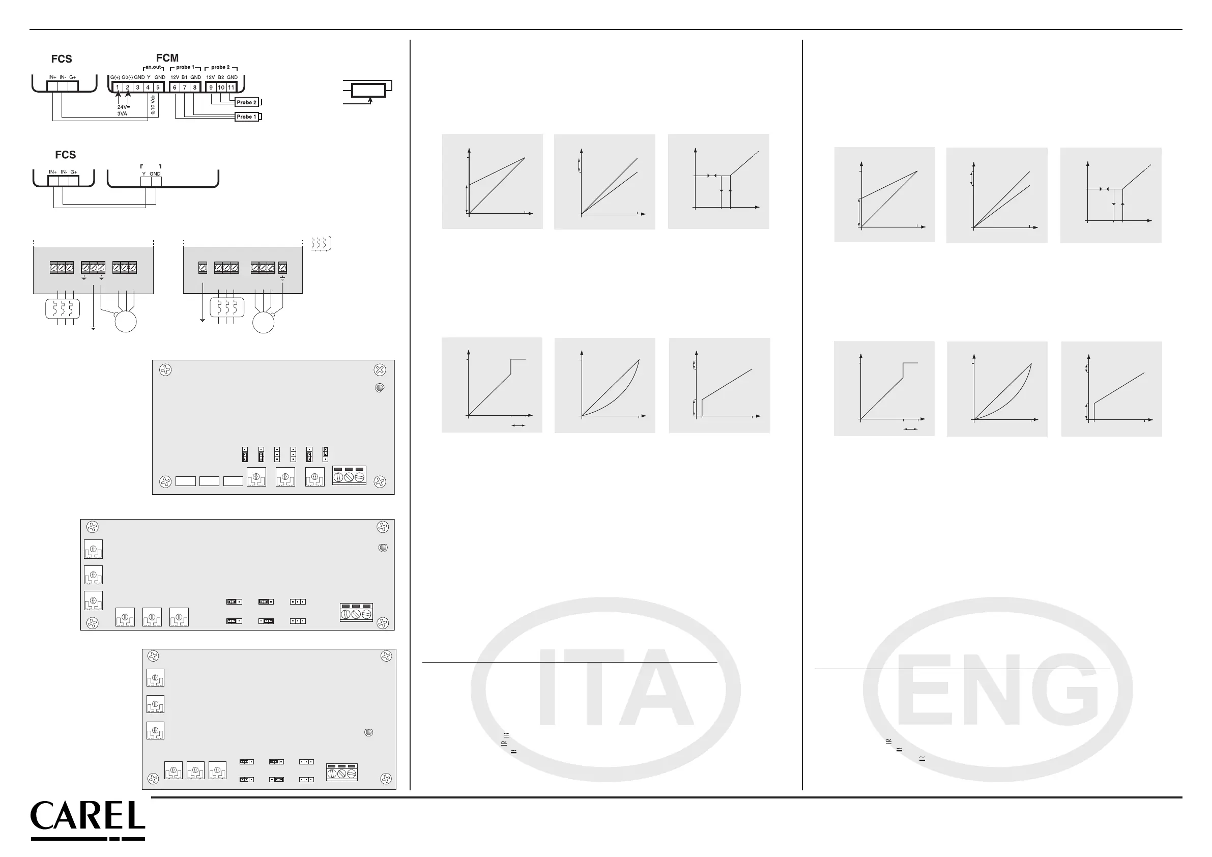
hysteresis of about 0.125 V for PWM control from μCH. Vice-versa, moving it to the indication MIN, the output vol-
tage, with a min. control voltage of 1V (0.5 V for PWM), remains at the value set using the MIN trimmer.
10 V/μCH mode: Moving jumper JP7 to the indication 10 V, the control signal must have a range from 0 to 10 Vdc.
Vice-versa, moving it to the indication μCH, the PWM control signal must have a range of 5 V.
THRESHOLD: Turning the THRESHOLD trimmer anti-clockwise, the value of the control voltage decreases (from
7 to 10 V with 0...10 Vdc control, or from 3.5 to 5 V with PWM control), above which the output voltage instanta-
neously goes to the maximum value; to avoid this, turn the trimmer clockwise.
Following, you will find a graph representation of the above-described situation, in MIN, MAX and CUT-OFF modes.
Tensione uscita
Output voltage
0%
0V
10% ...100%7,5%
modo CUT-OFF / CUT -OFF mode
min
...max
Segnale ingresso
Input signal
Tensione uscita
Output voltage
Segnale ingresso
Input signal
min
trimmer MIN / MIN trimmer
0%
0V
400V
(230V)
100%
200V
(115V)
Tensione uscita
Output voltage
max
trimmer MAX / MAX trimmer
0%
0V
100%
300V
(172V)
Segnale ingresso
Input signal
400V
(230V)
LIN/QUAD mode: If jumper JP9 is moved to the indication QUAD, the relationship between the variation of the
input signal and the voltage supplied to the load is quadratic-type. In practical terms, this achieves a “softer”
start-up of the load and significant variations in speed at the higher input signal values, meaning faster and faster
responses near to the upper limits of the control band. Vice-versa, if moved to the indication LIN, there will be a
linear proportional relationship between the control signal and the voltage supplied to the load, with slight varia-
tions in speed corresponding to significant changes in the control signal near the end scale.
Following you will find a graphic representation of the above-described situation, in THRESHOLD and LIN/QUAD
modes and an example of a combination.
modo CUT-OFF / CUT -OFF mode
Tensione uscita
Output voltage
Segnale ingresso
Input signal
min
max
esempio/example: MIN, MAX & CUT-OFF
0%
0V
100%10%
350V
(200V)
400V
(230V)
100V
(57V)
Tensione uscita
Output voltage
Segnale ingresso
Input signal
trimmer SOGLIA / THRESHOLD trimmer
0%
0V
400V
(230V)
100%70%
THRESHOLD
Tensione uscita
Output voltage
Segnale ingresso
Input signal
modo LIN/QUAD / LIN/QUAD mode
0%
0V
100%
400V
(230V)
Technical specifications
Three-phase power supply 400 Vac (230 Vac) +10%/-15%
Frequency 50/60 Hz
Driving signal (that can be selected by the jumper) 0/10 Vdc or PWM for μchiller series (5 Vpp)
Command signal voltage G+ 18/26 Vdc FCS3xx40xx, 24/33 Vdc FCS3xx23xx
Control signal voltage 50 mA max
Input impedance (control circuit) 10 KΩ
Power consumption (control circuit) 8 VA
Operating temperature -10T50°C (see temperature derating)
Storage temperature -20T70°C
Max. heatsink temperature 75°C
Ageing specification 60.000 h
Action-disconnection type 1C
Pollution degree of the controller Normal
Index of protection of the case IP55 / IP20
Period of electric stress across insulating parts Long
Classification according to protection against electric shocks class II at the 0/10 Vdc input terminal block (insulation of
4000 V between the input signal at very low voltage and
the device supplied parts) and class I as regards the
accessible parts.
All the models of the controllers are CE marked and comply with the EEC directives 73/23, 89/336 and successive amendments.
The essential requirements of the directives are satisfied by conformity to the following standards
NAME TYPE CONTROLLER COVERED
• CEI EN 60730-1 Safety FCS306****, FC309****, FCS312****, FCS320****, FCS340****
• CEI EN 50081-1 Residential Emissions FCS306****, FC309****, FCS312****, FCS320****
• CEI EN 50082-1 Residential Immunity FCS306****, FC309****, FCS312****, FCS320****
• CEI EN 55014-1 Emissions, Household FCS306****, FC309****, FCS312****, FCS320****
• CEI EN 55014-2 Immunity, Household FCS306****, FC309****, FCS312****, FCS320****
• CEI EN 50081-2 Heavy Industrial Emissions FCS340****
• CEI EN 50082-2 Heavy Industrial Immunity FCS340****
Notes on the maximum current leakage in the 20 A model: earth leakage current from the controller
- in normal operation Id 0.03 mA
- with one phase missing Id 5.95 mA
- with one phase only connected Id
11.3 mA
Notes on the voltage tests applied
The device is fitted with an internal EMC filter with two capacitors to earth. In the voltage test applied, these capacitors can be
temporarily bypassed, by removing the cable connected to the faston marked J1. At the end of the test, the cable must be con-
nected again.
al valore impostato tramite il trimmer MIN.
Modo 10V/μCH: Posizionando il ponticello JP7 in corrispondenza dell’indicazione 10 V, il segnale di comando deve
avere un’estensione da 0 a 10 Vdc. Viceversa, posizionandolo in corrispondenza dell’indicazione μCH il segnale di
comando PWM deve avere un’estensione di 5 V.
SOGLIA: Ruotando il trimmer SOGLIA in senso antiorario si diminuisce il valore della tensione di comando (da 7 a
10 V con comando 0-10 Vdc o da 3,5 a 5 V con comando PWM) al di sopra della quale la tensione in uscita si porta
istantaneamente al valore massimo, altrimenti ruotare il trimmer in senso orario.
Di seguito viene rappresentata graficamente la situazione appena descritta, nelle modalità MIN, MAX e CUT-OFF.
Tensione uscita
Output voltage
0%
0V
10% ...100%7,5%
modo CUT-OFF / CUT -OFF mode
min
...max
Segnale ingresso
Input signal
Tensione uscita
Output voltage
Segnale ingresso
Input signal
min
trimmer MIN / MIN trimmer
0%
0V
400V
(230V)
100%
200V
(115V)
Tensione uscita
Output voltage
max
trimmer MAX / MAX trimmer
0%
0V
100%
300V
(172V)
Segnale ingresso
Input signal
400V
(230V)
Modo LIN/QUAD: Nel caso il ponticello JP9 sia posizionato in corrispondenza dell’indicazione QUAD, la relazione
tra variazione del segnale di comando e tensione erogata al carico é di tipo quadratica. All’atto pratico si ottiene
una partenza più “dolce” del carico e delle variazioni rilevanti di velocità nei valori più alti del segnale di ingresso,
offrendo risposte sempre più rapide all’avvicinarsi del limite superiore della banda di regolazione. Viceversa, nel
caso sia posizionato in corrispondenza dell’indicazione LIN si ottiene una proporzionalità diretta lineare tra il
segnale di comando e la tensione fornita al carico con modeste variazioni di velocità relative a grandi scostamen-
ti del segnale di comando in prossimità del fondo scala.
Di seguito viene rappresentata graficamente la situazione appena descritta, nelle modalità SOGLIA, LIN/QUAD e
un esempio di combinazione.
modo CUT-OFF / CUT -OFF mode
Tensione uscita
Output voltage
Segnale ingresso
Input signal
min
max
esempio/example: MIN, MAX & CUT-OFF
0%
0V
100%10%
350V
(200V)
400V
(230V)
100V
(57V)
Tensione uscita
Output voltage
Segnale ingresso
Input signal
trimmer SOGLIA / THRESHOLD trimmer
0%
0V
400V
(230V)
100%70%
THRESHOLD
Tensione uscita
Output voltage
Segnale ingresso
Input signal
modo LIN/QUAD / LIN/QUAD mode
0%
0V
100%
400V
(230V)
Caratteristiche tecniche
Alimentazione trifase 400 Vac (230 Vac) +10%/-15%
Frequenza 50/60 Hz
Segnale di comando (selezionabile da ponticello) 0/10 Vdc o PWM per serie μchiller (5Vpp)
Tensione di segnale di comando G+ 18-26 Vdc FCS3xx40xx, 24/33 Vdc FCS3xx23xx
Corrente segnale di comando 50 mA max
Inpedenza d’ingresso (circuito di comando) 10 KΩ
Potenza assorbita (circuito di comando) 8 VA
Temperatura di lavoro -10T50°C (vedi declassamento in temperatura)
Temperatura di immagazzinamento -20T70 °C
Temperatura max dissipatore 75°C
Caratteristiche di invecchiamento 60.000 ore
Tipo di azione-disconnessione 1 C
Grado di polluzione del regolatore Normale
Grado di protezione involucro IP55 / IP20
Periodo di sollecitazioni elettriche delle parti isolanti Lungo
Classificazione secondo la protez. contro le scosse elettriche classe II alla morsettiera degli ingressi 0/10V (isolamento di
4000 V tra segnale d’ingresso a bassissima tensione e
parti in tensione del dispositivo) e classe I rispetto le
parti accessibili.
Tutti i modelli di regolatori sono marcati CE e conformi alle direttive comunitarie 73/23 CEE, 89/336 CEE e aggiornamenti successivi.
I requisiti essenziali delle direttive sono soddisfatti dalla conformità alle norme
NOME TIPO REGOLATORI COPERTI DA VERIFICA
• CEI EN 60730-1 Sicurezza FCS306****, FC309****, FCS312****, FCS320****, FCS340****
• CEI EN 50081-1 Emissione Residenziale FCS306****, FC309****, FCS312****, FCS320****
• CEI EN 50082-1 Immunità Residenziale FCS306****, FC309****, FCS312****, FCS320****
• CEI EN 55014-1 Emissione Amb. Dom. FCS306****, FC309****, FCS312****, FCS320****
• CEI EN 55014-2 Immunità Amb. Dom. FCS306****, FC309****, FCS312****, FCS320****
• CEI EN 50081-2 Emissione Industriale FCS340****
• CEI EN 50082-2 Immunità Industriale FCS340****
Note sulla massima corrente dispersa nel modello da 20 A: corrente dispersa verso terra dal regolatore
- funzionamento normale Id 0,03 mA
- con una fase mancante Id
5,95 mA
- con una sola fase collegata Id
11,3 mA
Note per la prova di tensione applicata
Il dispositivo è provvisto di un filtro EMC interno avente due condensatori verso terra. Nella prova di tensione applicata, tali con-
densatori possono essere temporaneamente esclusi togliendo il cavo collegato al faston siglato J1. Al termine della prova, il cavo
deve essere ricollegato.
Carel si riserva la possibilità di apportare modifiche o cambiamenti ai propri prodotti senza alcun preavviso.
Carel reserves the right to alter the features of its products without prior notice.
+050004070 rel. 1.5 - 16/12/2014
CAREL INDUSTRIES HQs
Via dell’Industria, 11 - 35020 Brugine - Padova (Italy)
Tel. (+39) 0499716611 – Fax (+39) 0499716600
http://www.carel.com – e-mail: carel@carel.com
L1 L2 L3 PE U V W
INPUT
OUTPUT
M 3
Alimentazione trifase
Three-phase supply
mod. 6-12-20 A
IN+
G+
IN-
10 K
Potenziometro
Potentiometer
Collegamento al modulo di comando FCM / Connection to FCM driving module
Collegamento di potenza / Connection to load
Scheda di comando FCS 9-12-20-40 A IP55 e 20-40 A IP20/ 9-12-20-40A IP55 and 20-40A IP20 Master Board FCS
CUT-OFF/MIN
10V/ûAC
INPUT
I/V
LIN/QUAD
60Hz/50Hz
MIN MAX SOGLIA IN+ IN- G+R1 R2 R3
POWER
SUPPLY
JP8 JP7 JP5 JP6 JP9 JP13
Scheda di comando FCS 6 A
6A Master Board FCS
R1
R2
R3
MIN MAX SOGLIA
CUT-OFF/MIN
10V/AC INPUT
I/V
LIN/QUAD
60Hz/50Hz
JP8
JP7 JP5
JP6
JP9
JP13
IN+ IN- G+
POWER
SUPPLY
Fig. 3b
Fig. 5a
fan
output
PWM
μchiller series
Collegamento ai regolatori della serie μchiller / Connection to μchiller series regulators
Fig. 3c
L1PE L2 L3 U V W
INPUT
OUTPUT
M 3
Alimentazione trifase
Three-phase supply
mod. 40 A
Fig. 4a
Fig. 4b
R1
R2
R3
MIN MAX SOGLIA
CUT-OFF/MIN
10V/AC INPUT
I/V
LIN/QUAD
60Hz/50Hz
JP8
JP7 JP5
JP6
JP9
JP13
IN+ IN- G+
POWER
SUPPLY
Fig. 5b
Fig. 5c
Scheda di comando FCS 12 A IP20
12A IP20 Master Board FCS
Magnetotermico di tipo C
Type C magnetothermal protection
Portata/Rate = 1,1 In
In=corrente nominale motore
Motor nominal current
Fig. 3a
 Loading...