OUT1: deve essere programmata come uscita di allarme atti-
va solo in caso di allarme di “Bassa”. Si deve quindi modifica-
re la dipendenza DIPENDENZA=C34 che passa da 1 a 9 (o
10 se si vuole lavorare con relè normalmente ON). I parame-
tri C35, C36, C37 non hanno più rilevanza e restano invariati.
OUT2: si svincolerà dal funzionamento DIFFERENZIALE
cambiando la DIPENDENZA da 1 a 2: quindi DIPENDEN-
ZA=C38=2. La logica è di tipo Direct e comprende tutto
P2, quindi INSERZIONE=C40 diventa 100, e DIFFEREN-
ZIALE/LOGICA=C41 diventa -100. St2 sarà ovviamente
impostato a 8 e P2 rappresenta la variazione minima
necessaria per riavviare l’unità, una volta che si è arresta-
ta per “Bassa” temperatura, es P2=4.
OUT3 e OUT4: negli strumenti con 4 uscite, il Modo 1
assegna ad ogni uscita una isteresi pari al 25% del differenziale
P1. Nell’esempio considerato le uscite effettivamente utilizzate
per la regolazione sono 2, per cui si vuole che l’isteresi di ogni
uscita sia il 50% di P1. È necessario quindi cambiare i
parametri INSERZIONE e DIFFERENZIALE/ LOGICA delle
uscite indicate in modo che si adattino alla nuova situazione.
In pratica si dovrà porre:
OUT3:
INSERZIONE=C44 passa da 75 a 50
DIFFERENZIALE/LOGICA=C45, passa da -25 a -50.
OUT4:
INSERZIONE=C48 resta a 100
DIFFERENZIALE/LOGICA = C49 passa da -25 a -50.
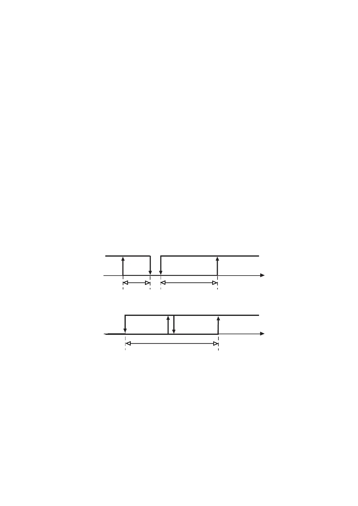
Il disegno riassume la logica di funzionamento della
regolazione:
Esempio 13
Si vuole pilotare 3 bruciatori di una caldaia per portare
l’acqua alla temperatura St1. È richiesta un’uscita di allar-
me che deve essere attivata nel caso in cui l’acqua superi
un limite di “Alta” temperatura o in caso sia segnalato un
blocco dell’impianto.
Soluzione: supposto che il segnale di blocco sia disponi-
bile come contatto pulito, si potrà utilizzare l’ingresso digi-
tale per la sua gestione. Si dovrà poi configurare un’uscita
come allarme (DIPENDENZA=5 o 6).
Il Modo di partenza può essere lo standard, ovvero C0=2.
OUT1: program it as active alarm output to be used in the
event of low temperature alarm; in this case modify
dependence (DEPENDENCE=C34) from 1 to 9 (or 10 if
you want normally open relays).You do not need to
modify C35, C36, C37.
OUT2: in order to make idle the DIFFERENTIAL function,
change DEPENDENCE from 1 to 2: DEPENDENCE=C38=2.
The controller will perform in the DIRECT logic and will
include the entire value of P2:Therefore old ENERGIZATION=
C40 becomes C40=100, and old DIFFERENTIAL/LOGIC=C41
becomes C41=-100. Set St2=8. P2 indicates the minimum
variation necessary to re-start the unit following a low
temperature condition (e.g. P2=4).
OUT3 and OUT4: when using 4-output controllers, setting
Mode 1 means to give each output a hysteresis corresponding
to 25% of the differential P1. In the example shown below,
there are 2 actual control outputs (OUT3 and OUT4) so
the hysteresis of each output should correspond to 50%
of P1. It is therefore necessary to change ENERGIZATION
and DIFFERENTIAL/LOGIC referrring to the indicated output
so as to meet the new application requirements.
In short:
OUT3:
ENERGIZATION=C44 changes from 75 to 50
DIFFERENTIAL/LOGIC=C45 changes from -25 to -50.
OUT4:
ENERGIZATION=C48 remains 100
DIFFERENTIAL/LOGIC=C49 changes from -25 to -50.
The graph below shows the new control logic:
Example no. 13
Control and regulation of 3 boiler burner units so as to
bring the water temperature to St1.You need one alarm
output that will energise in the event the water temperatu-
re rises above the “High” temperature threshold or in the
event the system locks.
Solution: Use the digital input (voltage-free contact) to
regulate the 'system lock' signal.Then configure another
output as alarm output (DEPENDENCE=5 or 6).
As for the Mode, there is no need to change its standard
setting, that is C0=2.
53

 Loading...