Le modifiche da apportare sono:
Modo di partenza: C0=2
ingresso digitale 1: gestione allarme con blocco uscite e
attivazione uscita di allarme.
C29=2 allarme immediato con Reset manuale;
C31=0 in caso di allarme da ingresso digitale tutte le usci-
te vengono spente.
OUT1:
uscita ON/OFF per comando del primo bruciatore:
INSERZIONE=C36=-33 DIFFERENZIALE/LOGICA=C37=33
(DIPENDENZA e TIPO DI USCITA invariati)
OUT2:
uscita ON/OFF per comando del secondo bruciatore:
INSERZIONE=C40=-66 DIFFERENZIALE/LOGICA=C41=33
(DIPENDENZA e TIPO DI USCITA invariati)
OUT3:
uscita ON/OFF per comando del terzo bruciatore:
INSERZIONE=C44=-100 DIFFERENZIALE/LOGICA=C45=34
(DIPENDENZA e TIPO DI USCITA invariati)
OUT4:
uscita ON/OFF d’allarme di “Alta” e da blocco esterno.
DIPENDENZA C46=5 (o 6 se si preferisce il relè normalmente
eccitato)
P26 = livello di “Alta” temperatura richiesto (Es. 90°C)
P27 = differenziale allarme (visto che l’allarme deve esse-
re assoluto, P27 deve essere positivo)
P28 = eventuale ritardo allarme temperatura e blocco
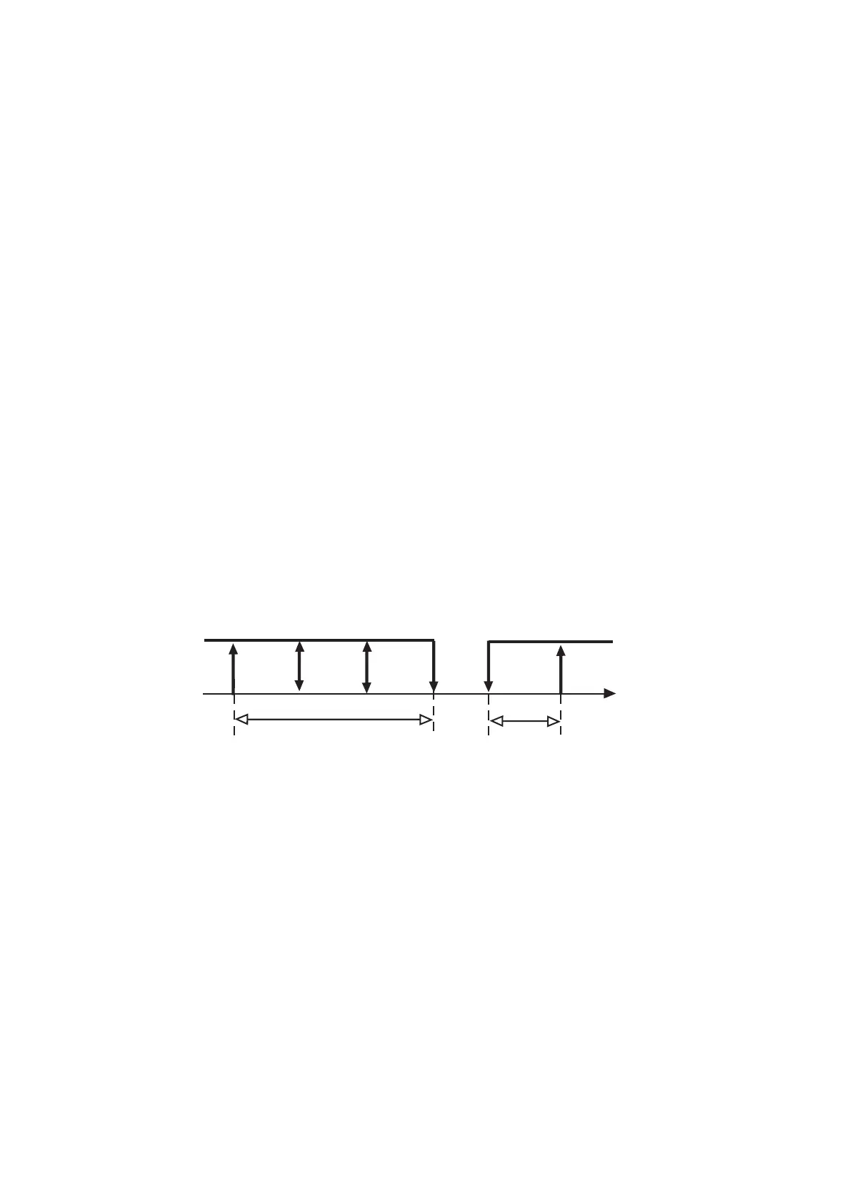
Il grafico raffigura la logica di funzionamento selezionata.
Esempio 14
In un impianto di stagionatura si controlli la temperatura
tramite un compressore (generatore di freddo) ed una
resistenza elettrica (generatore di calore). Il controllo deve
agire con una zona neutra di 3 °C attorno ad un set di 5 °C.
Il comando della resistenza dovrà essere di tipo PWM per
un inserimento proporzionale della potenza.
Soluzione: Modo di partenza: C0=3 salvare la modifica
uscendo dalla programmazione con PRG, rientrare in pro-
grammazione, P.W.77, ponendo C33=1;
St1=5°C, P3=1,5°C P1 e P2 stabiliranno il differenziale di
lavoro rispettivamente della resistenza e del compressore.
OUT1: comando della resistenza con funzionamento PWM;
TIPO DI USCITA=C35=1, per funzionamento PWM (DIPEN-
DENZA, INSERZIONE e DIFFERENZIALE/LOGICA invariati).
OUT2: uscita ON/OFF per comando del compressore:
resta invariata.
In short:
Starting Mode: C0=2;
Digital input no.1: alarm management with output disener-
gization and energization of the alarm output;
C29=2: immediate alarm, manual reset;
C31=0: in the event of off-normal condition, all outputs will
disenergise;
OUT1:
ON/OFF output to control the first burner unit
ENERGIZATION=C36=-33 DIFFERENTIAL/LOGIC=C37=
33 (Dependence and Type of Output remain unchanged).
OUT2:
ON/OFF output to control the second burner unit
ENERGIZATION=C40=-66 DIFFERENTIAL/LOGIC=C41=
33 (Dependence and Type of Output remain unchanged).
OUT3:
ON/OFF output to control the third burner unit
ENERGIZATION=C44=-100 DIFFERENTIAL/LOGIC=C45=
34(Dependence and Type of Output remain unchanged).
OUT4:
ON/OFF output for high temperature alarm and external
system lock.
DEPENDENCE C46=5 (or 6 if you prefer a normally ener-
gized relay);
P26=sets the required high temperature level (e.g. 90°C);
P27=alarm differential (P27 must be a positive value);
P28=time-delay (if any) before the activation of the tempe-
rature/system lock alarm.
The graph below illustrates the new control logic:
Example no. 14
Control and regulation of the temperature of a cold stora-
ge room by means of a compressor (cooling function) and
an electric heater (heating function). The controller will
develop corrective action in response to deviation from the
desired conditions, according to the set values, that is
neutral zone=3°C and set-point=5°C. The heater operates
in the PWM logic so as to obtain a proportional operating logic.
Solution: Starting Mode: C0=3: Confirm the modification
by exiting the programming field through PRG, then enter
again (password 77) and set C33=1; St1=5°C, P3=1.5°C
P1 and P2 represent the operating differential of heater
and compressor respectively.
OUT1: Control of the heater, PWM logic; TYPE OF OUT-
PUT=C35=1, PWM function (DEPENDENCE, ENERGIZA-
TION and DIFFERENTIAL/LOGIC remain unchanged).
OUT2: ON/OFF output for the control of the compressor
(unchanged)
54

 Loading...