42
ENG
ir33 universale +030220801 - rel. 2.1 - 21.06.2011
6.5.6 Enable logic on absolute set point & di erential
set point (parameter c19=5,6)
When c19=5 the value read by probe B2 is used to enable control logic in
both direct and reverse mode.
If c19=6 the value considered is B2-B1.
Par. Description Def Min Max UoM
c19 Operation of probe 2
5=enable logic on set absolute
6=enable logic on set di erential
Validity: c0=1 or 2
00 6-
c66 Enabling threshold in direct mode
Validity: c0=1 or 2
-50
(-58)
-50
(-58)
150
(302)
°C/°F
c67 Enabling threshold in reverse mode
Validity: c0=1 or 2
150
(302)
-50
(-58)
150
(302)
°C/°F
c66 Start enabling interval
Validity: c0=1 or 2
-50
(-58)
-199
(-199)
800
(800)
°C(°F)
c67 End enabling interval
Validity: c0=1 or 2
150
(302)
-199
(-199)
800
(800)
°C(°F)
Tab. 6.g
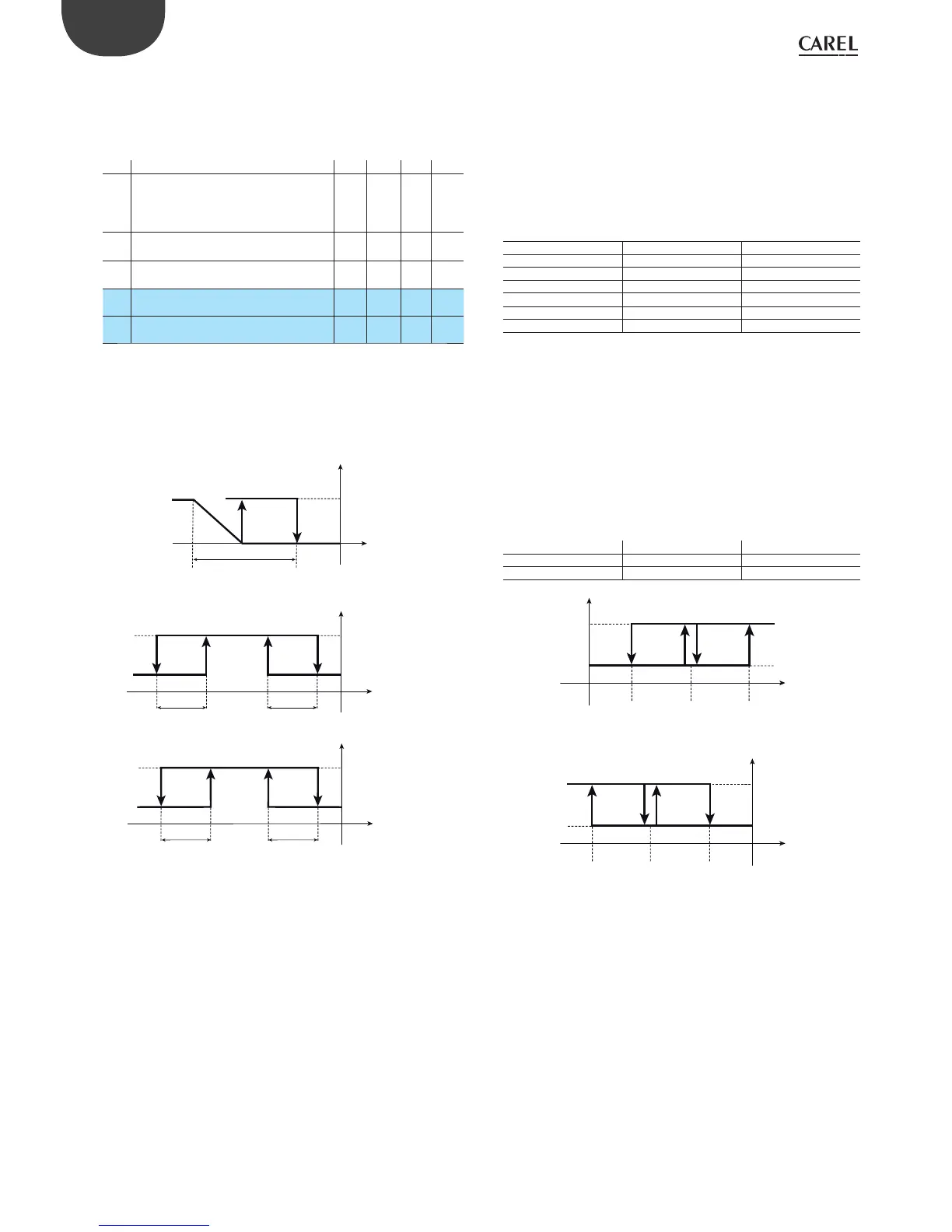
“Reverse” control with enable logic
Looking at the example of a controller with two outputs, one of which
ON/OFF and the other 0 to 10 Vdc. When the temperature read by probe
B2, if c19=5, or the di erence B2-B1, if c19=6, is within the interval (c66,
c67), “reverse” control is enabled on St1 and P1; outside of this temperature
range control is disabled.
St1
OUT2 OUT1
OUT
B1
P1
100%
0%
C19=5
c67-c65 c67
c66
c66+c65
ABILITAZIONE/
ENABLE
B2
ON
OFF
C19=6
c67-c65
c67
c66
c66+c65
ABILITAZIONE/
ENABLE
B2-B1
ON
OFF
Fig. 6.o
Direct” control with enable logic:
In this case too, a controller with two outputs, one of which a ON/OFF
and the other 0 to 10 Vdc. When the temperature read by probe B2, if
c19=5, or the di erence B2-B1, if c19=6, is within the interval (c66, c67),
“direct” control is enabled on St1 and P1; outside of this temperature
range control is disabled.
6.5.7 Independent operation (circuit 1+circuit 2)
(parameter c19=7)
Setting c19=7 control is “split” on two independent circuits, called circuit
1 and circuit 2, each with its own set point (St1, St2), di erential (P1, P2)
and PID parameters (ti_PID, td_PID).
This operation can only be set when c0=1 and 2 and is incompatible with
the activation of the operating cycle.
If c33=0, when setting c19=7 the control outputs are assigned to circuit 1
or circuit 2, depending on the model, as shown in the table below.
OUTPUT ASSIGNMENT
model circuit 1 (St1, P1) circuit 2 (St2, P2)
1 relay - -
2 relays OUT1 OUT2
4 relays OUT1, OUT2 OUT3, OUT4
4 SSRs OUT1, OUT2 OUT3, OUT4
1 relay +1 0 to 10 Vdc OUT1 OUT2
2 relays +2 0 to 10 V dc OUT1, OUT2 OUT3, OUT4
Tab. 6.h
Note that in general output 1 is always assigned to circuit 1, while output
2 can be assigned to circuit 1 or circuit 2. To assign any other output
to circuits 1 or 2, go to special operation (dependence=1 to assign the
outputs to circuit 1 and dependence= 2 to assign the outputs to circuit
2).
Example 1: con gure outputs 1, 2 to operate with “direct” logic using set
point and di erential 5, and outputs 3, 4 to operate with “reverse” logic
with setpoint -5 and di erential 5.
Solution: set c0=1, c19=7, in this way St1 and P1 depend on probe B1 and
St2, P2 depend on probe B2. In addition St1=+5, P1=5 and St2=-5, P2=5.
Then activate special operation (c33=1) and set the activation and
di erential/logic for outputs 3 and 4 as follows:
OUT 3 OUT 4
Activation c44= -50 c48= -100
Di erential/logic c45= +50 c49= +50
Tab. 6.i
7,5 10St1=5
B1
ON
OUT1 OUT2
OFF
- 7,5-10 St2= - 5
B2
ON
OUT3OUT4
OFF
Fig. 6.p
 Loading...